A couple of years back, we developed a serious rear main oil seal problem with our Northern Lights 12 kW generator. Oil was being sprayed all over the inside of the generator enclosure and running down the block. It was a real mess. Clearly the seal needed replacing, but it’s both a big job (notes below) and one that required parts we didn’t have at the time.
I’m an engineer, and am always interested in the underlying phenomena and what caused it. So we ran a series of experiments, trying three different solutions to the problem in order to learn more and possibly mitigate the problem.
This is the third in a set of articles discussing our rear main oil seal leak. The other two are:
Solution 1: Neutral Pressure
Whenever an engine has a serious oil leak and, especially when the leak worsens quickly, excess crank case pressure is a likely contributor. This can be caused by excess blow-by due to failing rings or other internal engine problems, but the more common cause is plugged or faulty crankcase ventilation systems.
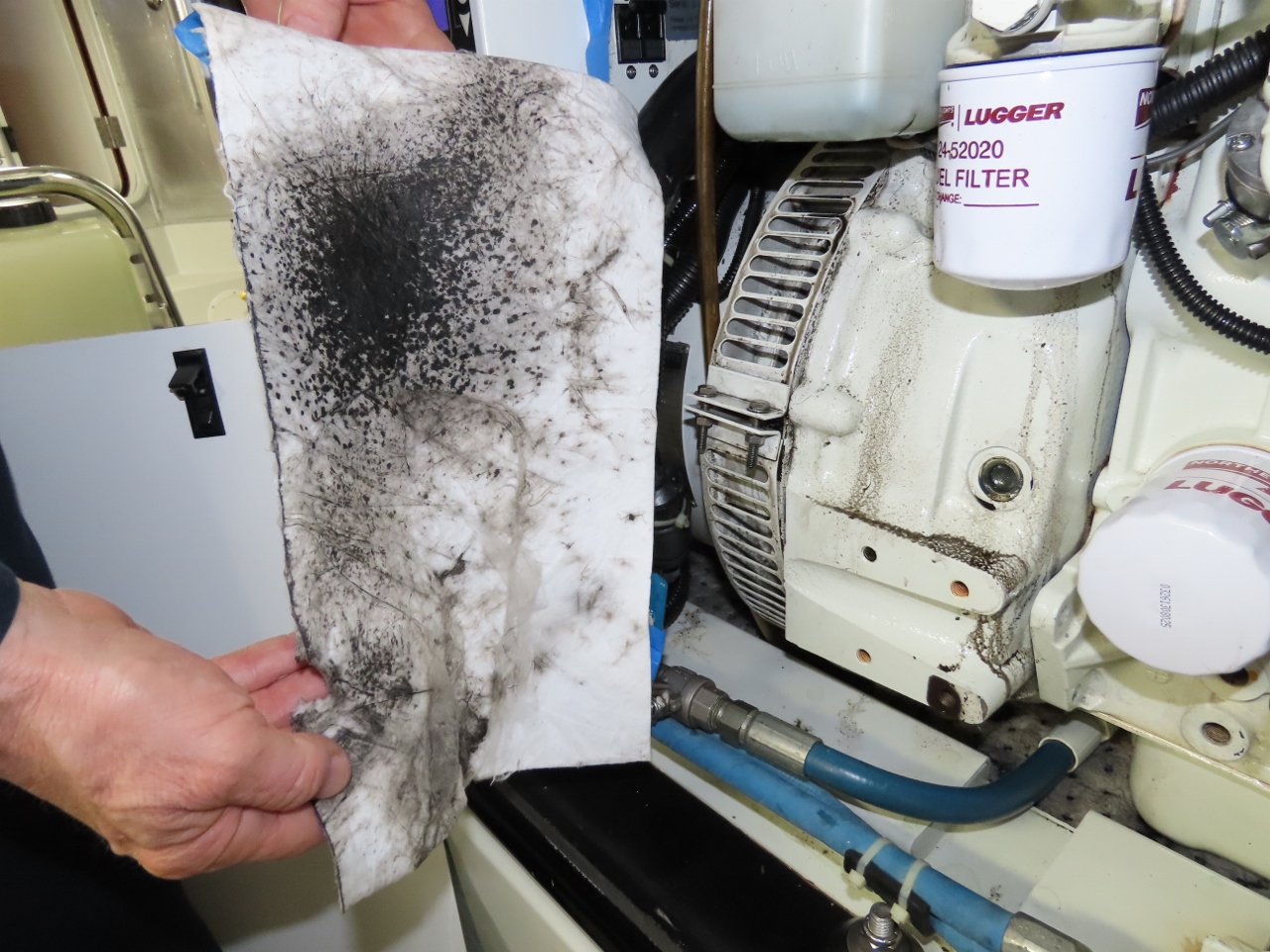
With a manometer, the internal crankcase pressure measured at 1.17 inches H2O in normal operation (see Gen Rear Main Oil Seal). This is 0.042 PSI, so a very slight positive pressure, which is as designed. But 1.17 inches of pressure is still fairly high, and if a seal was aging it would certainly be enough to cause it to leak. So I wanted to see if it would leak less with neutral pressure in the crankcase rather than slightly positive.

We implemented a zero-pressure crankcase by folding a shop rag into fours and hose-clamping it over the oil fill hole with the oil fill cap removed. This gave four layers of rag to prevent oil mist problems in the engine room while otherwise allowing a neutral pressure crankcase.
Neutral pressure made a big difference to the amount of oil sprayed into the generator enclosure. Where oil previously was thrown around everywhere, it was now down to a light misting with some minor build-up of oil on the grill that surrounds the generator cooling fan. The difference was remarkable. It immediately dropped back to only 5-10 of what is was leaking before, and it continued to just keep getting better. It was likely the case that the oil leak completely stopped, and what we were seeing was just the residue of the oil already in the flywheel and in the bell-housing continuing to leak out.
Solution 2: Catch bottle
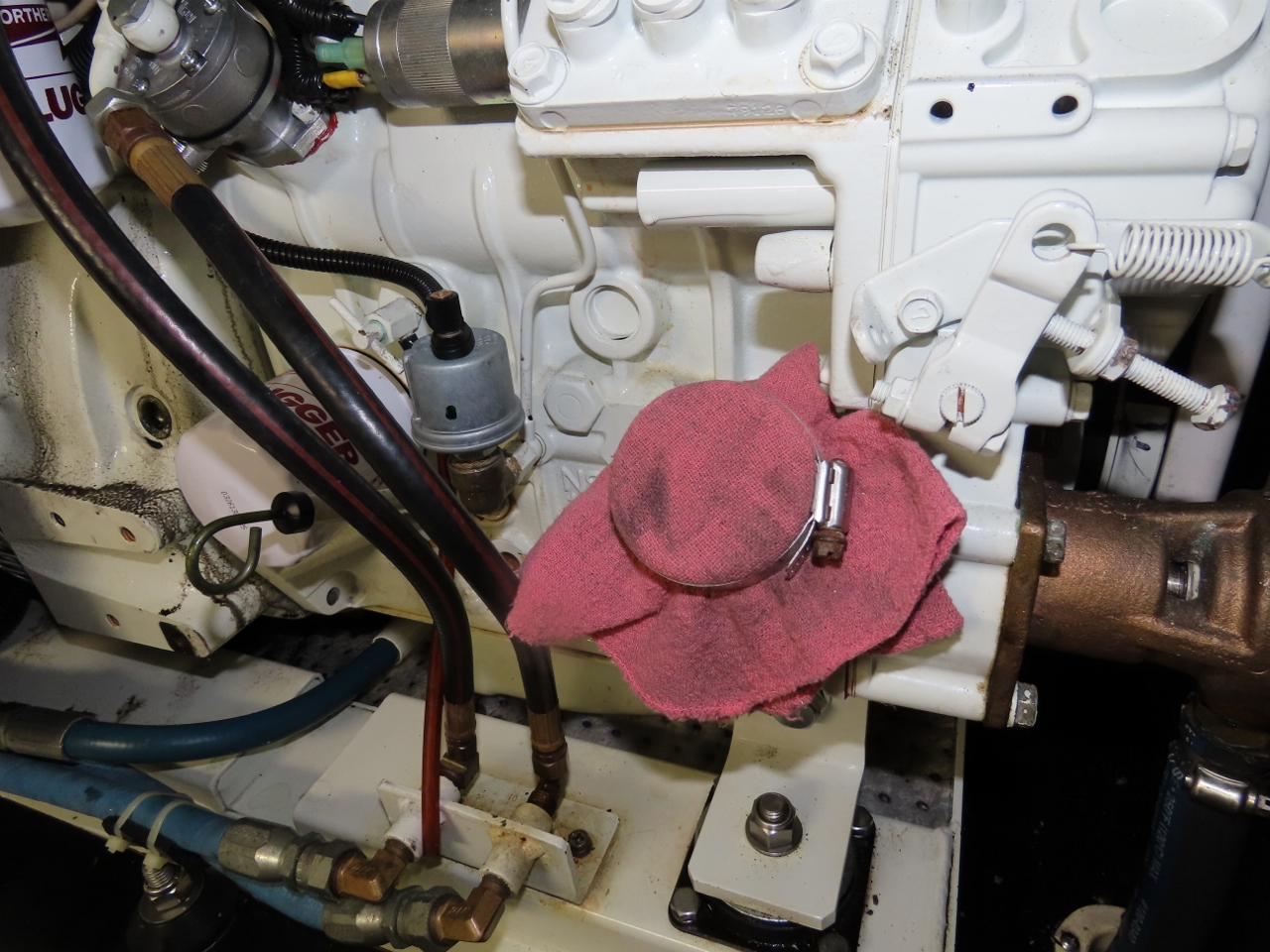
The rag solution was effective and a good way to test, but not particularly attractive. For a longer-term solution, I drilled a hole in the oil filter cap, taped the hole, installed a hose barb, and vented that into an oil catch bottle. At this point, the oil leak had completely stopped.
This configuration is cleaner, and the only service it needs is to drain the bottle every year or so. The only downside of this approach is the crankcase emissions are released into the engine room. It wasn’t really a problem, but I didn’t love the slight odor, so did one further experiment.
Solution 3: Negative Pressure
Venting the crankcase as described above eliminated the oil leak entirely, and the oil catch can isn’t particularly ugly or difficult to maintain. But it did give the engine room just a slight smell of diesel, so I decided to try one further experiment.
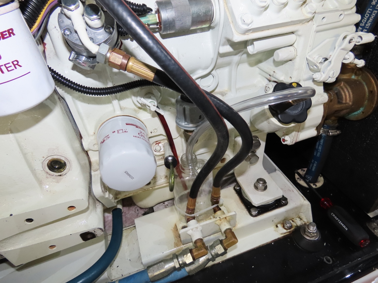
In this case, we’re going to try venting the crankcase directly into the intake manifold, so any of the crankcase vapors are going to be burned. And it has the added advantage of running just a slight bit of negative pressure in the crankcase.
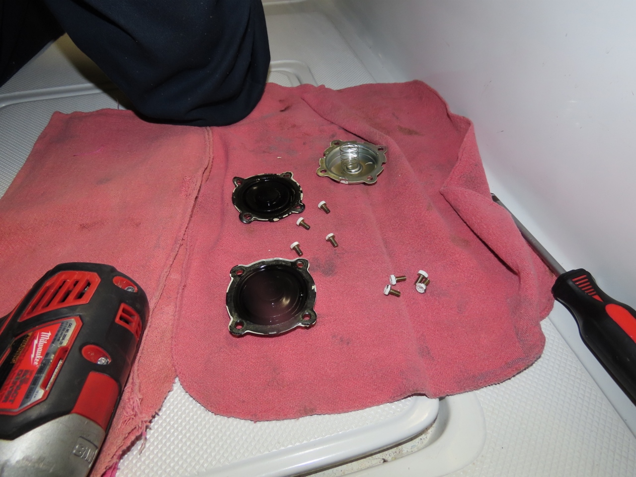
The Northern Lights crankcase ventilation system is a nice design where there is first an oil mist coalescing screen and then a diaphragm valve with a very light spring that holds the diaphragm closed. When slight pressure in the crankcase builds up, it’s vented into the intake manifold where it’s pulled back into the cylinders for combustion. This is a well-designed system and yields an operating crankcase pressure of just over 1 inch H2O.
 |
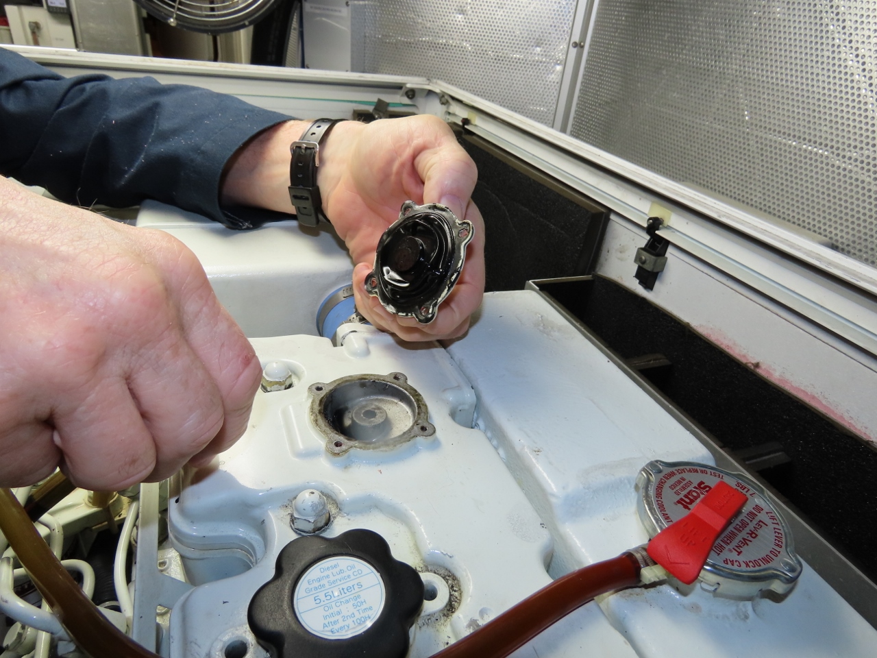 |
This system has the upside of being better for the environment, is legally required in many jurisdictions, and it smells better in the engine room. The downside of the approach is the spring requires measurable positive pressure, and as seals get old, even a slight positive crankcase pressure can lead to quite severe leaks.
 |
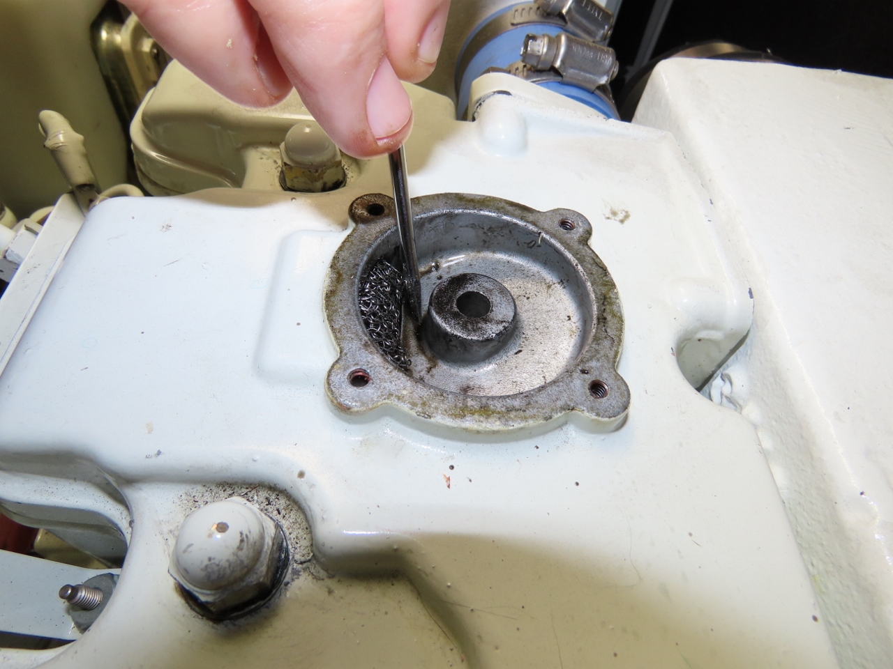 |
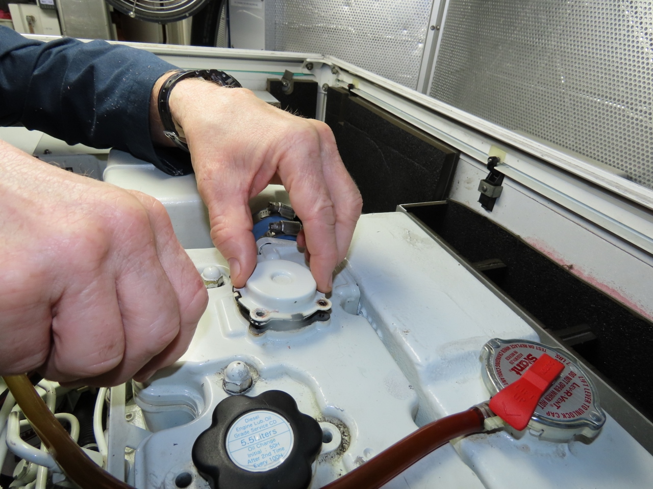
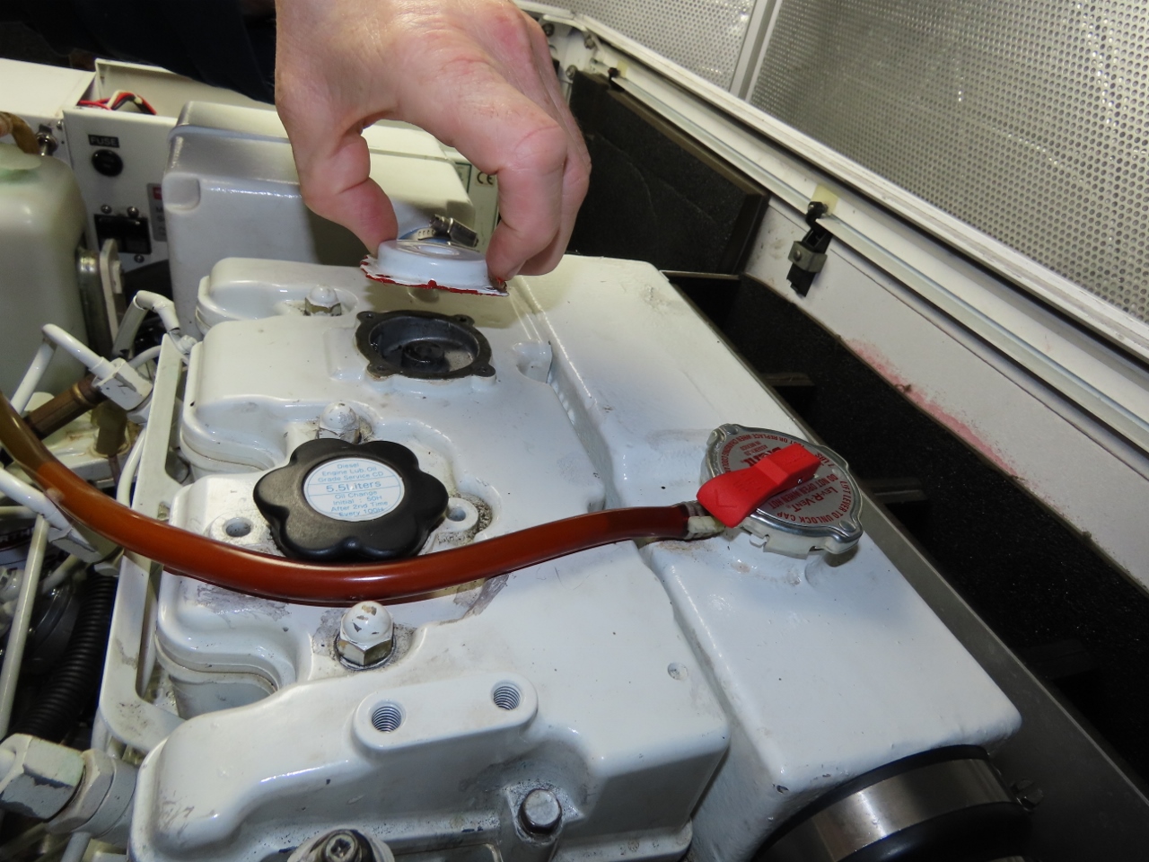
In this third and final test, I removed the crankcase ventilation diaphragm and spring and just sealed the cover to the valve cover with Permatex Orange. This allowed the crankcase to have zero to slightly negative pressure since the air filter and intake hose have some slight resistance to flow, dropping the intake manifold pressure just slightly below atmospheric.
 |
 |
It’s a nice configuration that I ran for thousands of hours. While not clearly better than our previous experiments, since none of them leaked, it’s at least as good. To fully evaluate this approach, more testing hours are required, but it appears excellent and the leak is gone.
Changing the Seal
We ended up not needing to change the rear main oil seal (see The Case of the Missing Oil Leak). But for those who do need to do the job, Ron and Nancy Goldberg did an excellent job of writing up the process from their Nordhavn 50 Duet, and were happy to share the instructions more broadly:
Our generator is a 12KVA (NL 843NK). We changed our oil seal in Tahiti with the assistance of a local mechanic who furnished a 10 ton chain hoist. Gale Plummer on the N57 Worknot replaced the oil seal on both of his 15 KVA generators and I asked him for advice before I started. Not all of it was applicable to my situation but I have pasted his original email at the bottom of this email.
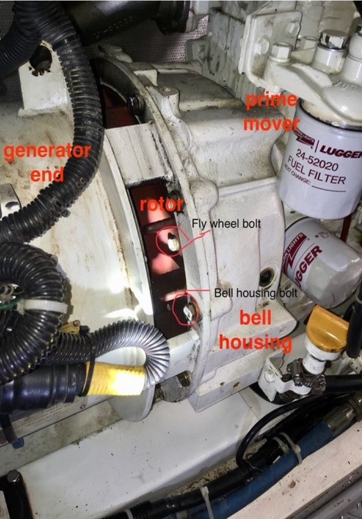
I have documentation for the PX-300K1 series generator end as well as a workshop manual for the NL prime mover. They contain important bolt torque specifications and are useful for overall orientation to the task.
Apart from the oil seal itself, the only special items that you might need: 1) universal swivel sockets; 2) chain hoist; 3) crowfoot wrench set; 4) Electric impact wrench. Item #1 is for accessing the bolts that secure the generator rotor to the prime mover flywheel. I did not have universal swivel sockets, only a universal swivel adapter that could be placed between the socket wrench and the socket. This set-up was too bulky to be useful. I muddled along anyway, but it took much longer. I describe this process a bit more below and have a picture that illustrates the issue. Item #4 makes it easier to undo the flywheel bolts, but I imagine you could get by without one.
The need for a chain hoist is obvious unless you can do what Gale Plummer did: he constructed long wood supports that were used to slide the generator away from the prime mover once the two components were decoupled. This approach did not work on my boat– thus the chain hoist.
The most important tip I can offer is make damned sure the oil leak is not coming from the valve cover. This can be a subtle problem, without obvious staining on the engine. I will sheepishly admit that after the seal was replaced (and it was in terrible shape, so it either was failing or would fail soon) I STILL had some oil leak. It seemed not as bad (perhaps this was wishful thinking), but it was still there. I wedged a folded oil absorbent pad between the generator and the prime mover to capture any oil seepage from the valve cover and this solved the problem. I subsequently installed a new valve cover gasket, threw away the oil pad, and have had no problems since.
Before working on the seal I completely disassembled the sound shield (and threw it away, but that’s another story), disconnected the exhaust plumbing and the electrical cabling to the generator junction box. Because of my engine room topography, I had to unbolt the Vernalift muffler and move it out of the way. Basically, I cleared the decks. Also, you need to somehow support the bottom of the generator so that the mounts can be undone.
The generator comes off as a complete component, with the rotor retained within the housing. The end of the rotor that is opposite the prime mover is supported within a bearing that is held within the end of the generator housing. This bearing has a service life of 10,000 hours (according to the documentation for the PX-300K1 generator series). Our gen has about 5000 hours, and we did not replace the bearing. It might be something you want to consider.
The ventilation screen gets removed to access the bolts that hold the rotor fan to the flywheel. These bolts are challenging, and this is where the universal swivel socket set could be useful. I believe the necessary size socket is 10 mm, but don’t hold me to that. In the absence of a universal swivel socket set, patience and small hands can get the job done. You may need Jennifer’s technical assistance.
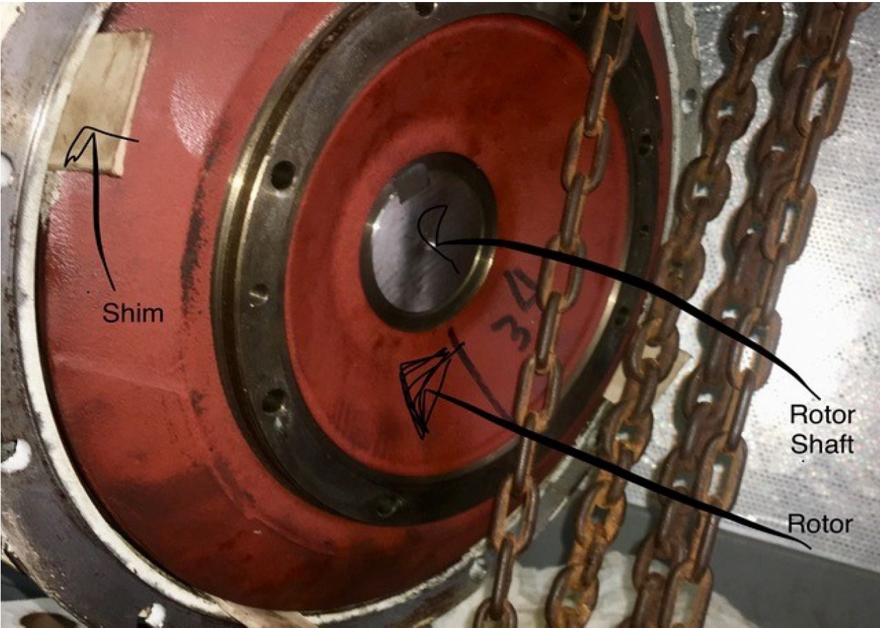
Before unbolting the rotor, I recommend placing some shims between the bottom of the rotor and the generator housing, to prevent side motion that could damage the stator.
Once the rotor bolts are out it just remains to undo the bolts that attach the generator housing to the bell housing of the prime mover. The rotor bolts and generator housing bolts are shown in the attached picture.
At this point the generator can be separated from the prime mover.
The next picture shows the rotor end of the generator with shims wedged in.
Once you get the generator off, the only remaining disassembly is the flywheel and the bell housing. The flywheel is VERY heavy. Take care not to lose the spring pin associated with the flywheel. Finally you have access to the oil seal. It was easy to pry out, but perhaps that is because the sealing surface was in such bad shape. We did not need to resort to sheet metal screws or anything of that nature. I have pictures of the old seal and the new seal below:
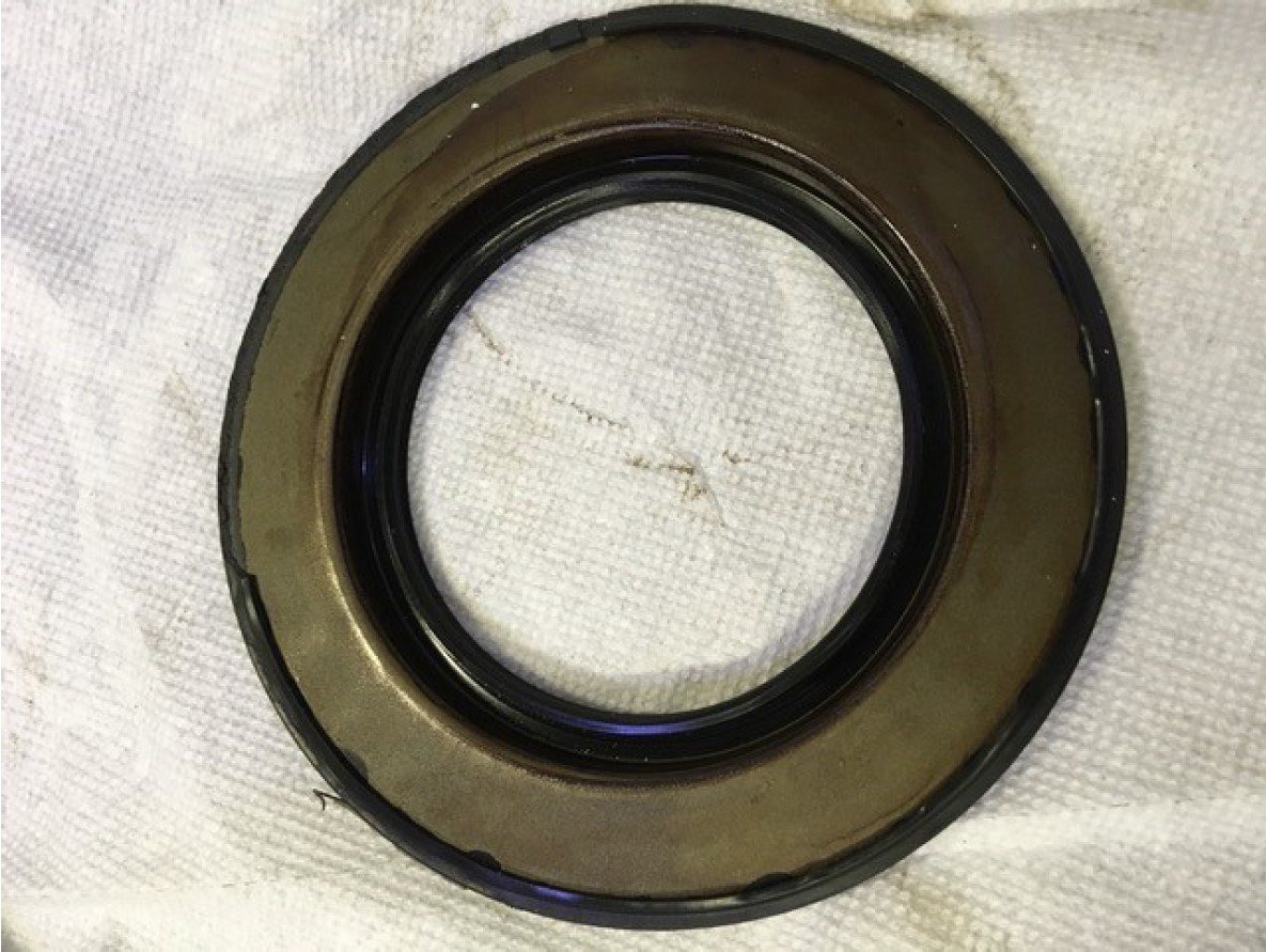
The outer rubber on the old seal (above) has become hard and brittle, and in some areas has broken away from the seal.
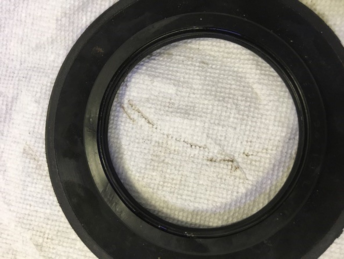
I had very light scoring on the crankshaft from the old seal and this was cleaned up with very fine emery cloth. The surface of the shaft was then carefully cleaned with WD-40 to wash/wipe away any residual abrasive material. The new seal just pops on.
Getting everything back together is nearly as much fun as taking it apart. Take note of the torque specs in the Northern Lights workshop manual and the PX-300K1 document. I will admit that getting the rotor properly lined up and re-bolted to the flywheel was probably the most challenging task.
Ron Goldberg
MV DUET
Below I have pasted the original email from Gail on Worknot:
THE GENERATOR must be split, the flywheel bolts are a little difficult as well as the lower outside bolt on the barrel. Crows foot wrenches, 10mm universal socket, mirror and a fan are required.
Flywheel and bellhousing must be removed. Flywheel is very heavy. Mark the position of the crankshaft and the generator rotor so you can fit the drive bolts back in place. Have a tool to rotate crank as the bolts cannot be accessed from the top.
Cut several tapered shims about 4” x 1.5” x 1/4”. These wedges are driven into the generator rotor fan to keep it stationary and prevent the rotor from contacting the stator.
Cut supports 2- 1” x 4” about 4” Long. These are placed vertically under the engine oil pan at the rear on each side. Try and span 2 oil pan bolts.
Was able to use 15” long timbers about 2” x 3” to extend the engine rails past the generator end. Using a pry bar and some shims was able to remove flywheel to rotor bolts and slide the generator back without removing the wiring. Used a 3/8” drive battery impact (no need to hold crankshaft with impact- use torque wrench to reinstall) to remove flywheel bolts. The length of the impact is the distance you need to slide the generator back +/- 10″.
DONT LET THE GENERATOR SLIDE OFF THE RAILS. No lifting device needed.
Be sure to oil the face of new seal, inspect the seal surface of crank. Gently polish in circular motion if needed.
Aligning the rotor bolts and tightening the bottom stator to bell housing bolts is the challenge.
Gale Plummer
WORKNOT N5715
www.worknotatlast.blogspot.com
If your comment doesn't show up right away, send us email and we'll dredge it out of the spam filter.