One of the things we really like about our more flexible power system is it allows us to run on shore power connections that deliver less than our peak power requirements. The shore power charges the house bank and 6 kW, 240V 60 Hz inverter supplies the peak capacity needed to run larger appliances such as the dryer and oven while a 4kW 120V 60 Hz inverter powers the rest of the house loads. For example, while plugged into only 16 amps from shore, we can frequently draw more than twice that. As long as our average draw is less than the shore power available, we keep up fine and never need to run the generator at dock. We just need to give the batteries time to recover after the dryer or oven is used for an extended period.

As we crossed the Pacific, Indian and Southern Atlantic oceans, spending time in the South Pacific, New Zealand, Australia, South Africa and the Caribbean, we never saw less than 16A at 240V and our power system worked well. It wasn’t until we later reached Europe that we had any reason to modify this system. The first time where we found running on a 16A service an inconvenience was a cold November visit to Liverpool, UK.

When the Liverpool air temperatures dropped down to the low 40s F or into the 30s (2-6 C), our electric heat was on more often. Our average power requirement rose, eventually exceeding the 16A available from shore. When this happens the batteries begin a slow but steady discharge. The easy solutions are to heat a smaller part of the house, heat to a lower temperature, or just switch over to the diesel heat. The latter solution of just using the diesel heating system works great, but over longer periods of time, it consumes a lot of diesel. This isn’t really a big problem, but is slightly less cost-effective than running on shore power, and it’s a hassle to fill up the diesel tanks more frequently. Also, we like the option value of full tanks, so we prefer not to use up our fuel at the dock.
A combination of concerns caused us to look for a shore-related solution: 1) we’d been told that some docks in Norway have only 8A service and there is no way we can run on 8A, and 2) we planned to spend four months in Amsterdam the next winter and the marina we were looking at has only a 16A service. We like to be toasty so, over the course of four months, that will end up consuming a large portion of our on-board fuel. So we investigated solutions that would allow us to use 2x 8A when only an 8A service is available or 2x 16A when it’s cold and we don’t want to run the diesel furnace at the dock.
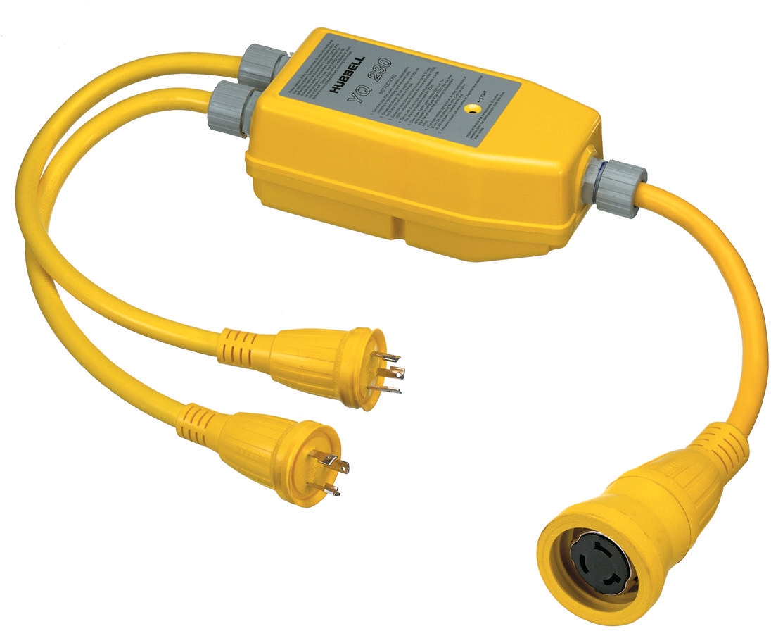
The obvious solution is to combine the two low-amperage connections. In North America we’ve used a Hubbell Y-adapter to safely combine two oppositely-phased 120V 30A connections to produce a single 50A 240V connection. But combining 240V power connections only works when they are phase-aligned, and this isn’t allowed by most, if not all, local European electrical codes.
Dirona is equipped with 2 Mastervolt Chargemaster 24/100-3 100A chargers, so a better and safe solution is to split our charging system supply bus in two. The existing shore power connection would feed one charger and a second shore power connection would feed the other charger. Each charger, when producing the full-rated 100 amps, consumes just a bit more than 13A. So with two shorepower connections of 16A each, neither would be overloaded even when the charges are running at full-rated output. If at a dock with only an 8A service, the two chargers’ output can be adjusted downward through the user interface to only draw 8A so we can still have 16A for use on the boat. Using this approach we can run on almost any shore power configuration no matter how small. In the picture at the top of this post, we are plugged into two 6A services along the Gota Canal in Sweden.
Electrical Design
The three major changes we made to our charging system in this project were:
- Add a second 240V shore power connection in the cockpit
- Build a control box to manage the power flow to the chargers
- Integrate the new shore power connection into our Maretron display and automation systems
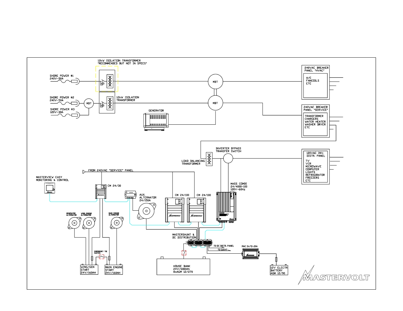
The diagram below shows Dirona’s charging and power distributions system as delivered, with the changes we made for the first two items shown inside the red dashed line. (The diagram doesn’t include the 240V inverter and related modifications we made earlier.)

Shorepower Connection
As delivered, Dirona actually had three shore power connections, visible at the upper left of the electrical diagram. The main charging connection is the middle one, rated for up to 50A at 240V. The bottom connection is rated for 30A at 120V. The top connection provides an additional 240V-50A supply, but only to the HVAC system. We’ve never found this one very useful, because it only feeds the HVAC system, and what we really want is two connections into the charging system rather than feeding the HVAC system. And our HVAC system isn’t rated to run on 50 Hz, so this connection is not useful in most parts of the world.
In this project, we added a second shorepower connection that feeds just the second charger. We’ve annotated the diagram to show how the second shore power connection fits into the design. Normally both chargers are fed from the selected source on Battery Charger Selector in the pilot house (described here). The new design adds a switch before charger 2 that allows the charger to be powered from either the designated source, or the new shore power connection.
In the pictures below, James is installing the new 16A breaker for the additional shore power connection in the breaker box inside the starboard cockpit locker. The breaker box cover is on the floor at right in the second picture.
 |
 |
Below are pictures of the breaker box with this portion of the job complete (before and after labeling), with the blue cable for the new 16A connection visible extending from below the box. The left breaker is the 30A breaker for the 120V AC shore power connection and the breaker on the right is the 50A breaker for the primary 50A 240V shore power service. The middle breaker is the new 16A breaker for the second shore power connection. The new 16A breaker replaces the one for the HVAC shore power connection that we don’t use. We also added a galvanic isolator for the new 16A connection.
 |
 |
The next phase was installing the actual plug for the new charging connection and wiring it into the breaker box. We installed the connection below the existing row of shore connections, from left to right, TV and phone, 120V AC shore power, and the disabled HVAC shore power.
The first picture below shows the new socket. At the time of initial install, we only had a female socket on board, so we temporarily used that until we had the proper polarity connection available. In the second picture below, we are testing the service. The wires run to the breaker behind the locker door and then below, but the below deck wire pulls haven’t yet been completed.
 |
 |
Control Box
To manage the power flow to the chargers, we built the control box shown below. The box cover has a set of four lights that when lit indicate the state of the shore power system:
- Left green: shore power 1 is powering charger 1
- Right green: shore power 1 is powering charger 2
- Left red: shore power 2 is powering charger 2.
- Right red: shore power 2 is enabled.
 |
|
| Control box to manage power flow to the chargers | |
When the two green lights are on, for example, this means that the original 50A 240V shore power connection is powering both chargers. This reflects how the system worked when we plugged into shore power prior to adding the new shore power connection. The big change is that charger 2 can now be powered by either shore power 1 or shore power 2 (but not both—this is prevented via electrical interlock). When we are charging via the new shore power 2 connection, the two red lights will be on, and optionally the leftmost green light if we are using the original shore power connection as well. The second picture above shows the light state when we have both shore power connections in use.
Beneath each light is a rocker switch that controls the state of the corresponding indicator above it. The switches can be in one of three positions: auto control (switched left), forced off (switched centrally), or manually on (switched right). The auto control setting allows our control systems to automatically manage the charger sources, for example by sense power at shore power 2 and switching charger 2 to that source. Without the automation system, the system can still be used by explicitly setting the rocker switches to either off or manual.
 |
|
| Control box interior | |
The inside of the control box is shown above. The state of the four contactors along the bottom is reflected in the lights on the front of the box. At top center is a Maretron ACM100 alternating current monitor for the shore power #2 connection to measure voltage, amperage, total kWh etc. Switching and sensing relays to control the charging configuration are on either side of the ACM 100.
Whether automatically or manually controlled, the system is fully interlocked so that two shore power connections into charger 2 can’t be inadvertently combined. If the contactor for charger 2 via shore power 1 is powered, this disables the contactor supplying power via shore power 2, and vice versa.
In order to manage the chargers via the control box, we needed to insert the box between the chargers and their power feed. This isn’t hard, but it meant that everything needed to come out to give charger access. The two chargers are mounted one above the other in the starboard side of the lazarette. In the left picture below, we have pulled them forward to start the rewiring. In the first picture at right below, we are wiring in the control box. The second picture at right shows the final completed job with the control box mounted to the right of the top charger.
 |
 |
 |
|
| Installing control box between chargers and power feed | |
The finished product shows at a glance if the system is online in automatic mode, manual mode, or forced off. It also shows if the chargers are powered and, if so, whether it’s from the house or from the second shore power connection. This is also remotely visible from the pilot house.
Monitoring and Control
We updated our N2KView “Moored” display to shows both “Shore 1” and “Shore 2”. The screen shot below shows the state of the system when we are plugged into two 16A/250V 50Hz connections. The two white indictor lights at bottom, slightly right of center indicate both are active at 50Hz (green indicates 60Hz). The amperage draw is 13 on Shore 1 and 12 on Shore 2 (lower right) and the voltage is 223 on Shore 1 and 225 on Shore 2 (numeric readout left of amperage). We are drawing 14A on the 240V inverter and 7A on the 120V inverter with the batteries charging at a positive 5.5A (near bottom of second column). Normally with this kind of draw and only a single 16A connection, the batteries would be discharging in a big way.

The system is fully functional in manual mode as described above, but we also added support to control the system remotely and automatically through a Raspberry Pi integrated into our automation system. The Raspberry Pi senses the availability of power at each charger and the second shore power connection and switches between them as needed.
The automation system was already setup to start the generator should we lose shore power and the batteries drain sufficiently. We also added support to switch charger 2 back to the original circuit should this happen when charger 2 is powered through the new shore power connection. This way the generator can use both chargers to charge the batteries.
System in Use
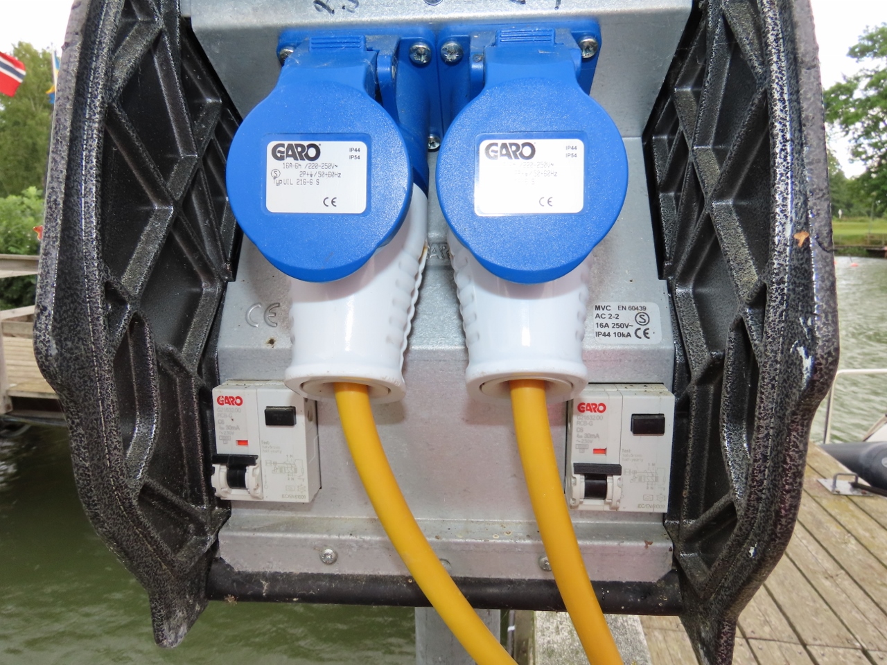
The system has worked flawlessly and we absolutely love it. The pictures below show the system in use in our winter berth in Amsterdam. On the left in the first picture, our built-in 50A/240V power cord leads over the transom (from the Glendinning shore power cord retractor outlet) into an adapter that connects to a 16A/240V extension cord. And on the right we have connected a second 16A/240V extension cord directly to the new shore power adapter, led the two orange extension cords over the transom, and plugged them into the top two 16A receptacles on the shore power pedestal behind the boat.
 |
 |
| The dual shorepower system working as designed in Amsterdam over the winter | |
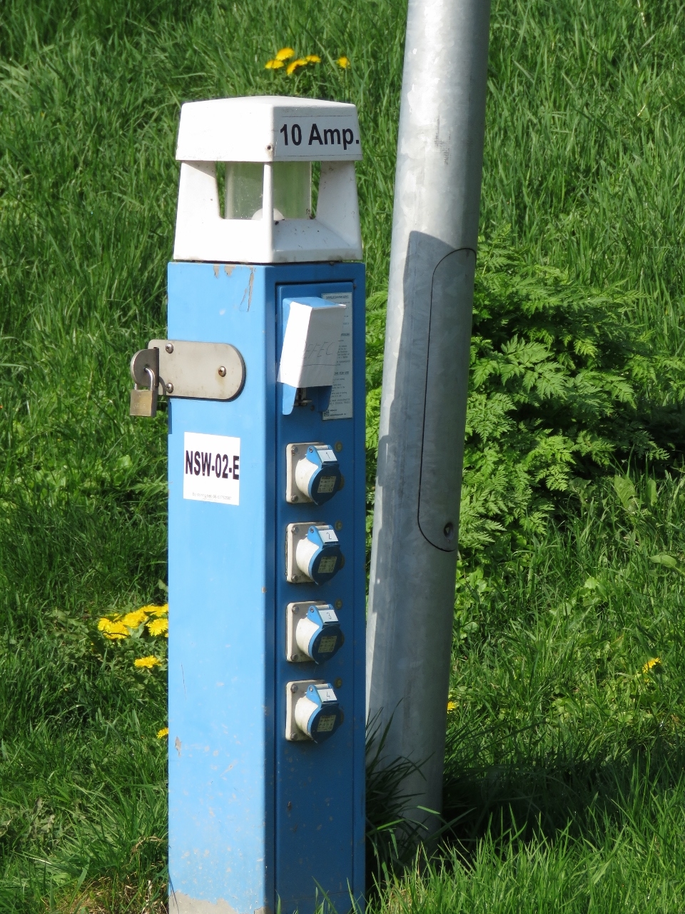
The dual shorepower system met its design point of allowing us to comfortably power Dirona with two 16A connections during the winter in Amsterdam, but also turned out to be super-useful for our subsequent Baltic cruise. The entire time in Sweden we saw at most 10 amps, so could plug into two for a 20-amp draw, as pictured below in Kalmar, Sweden. And on Sweden’s Gota canal, pictured at the top of this post, the shorepower connections were only 6 amps. It was amazing to see a fairly power-intensive boat able to run on 6-amp connections.
 |
 |
| Plugged into two 10A connections in Kalmar, Sweden | |
Unexpected Advantages
The new system also had some unexpected advantages in allowing us to deal more flexibly with challenging shorepower situations. Voltage sag was a common problem in many Baltic marinas. Pictured below is our berth in Helsinki, where we are plugged into dual 16A connections. The shore power on this dock has excessive voltage drop and the voltage can drop down to as low as 195 volts at higher loads. Managing this situation now is easy. We just adjust our draw down to whatever the dock can support, in this case 11 amps, and the house continues to run as well as ever on the inverters with the boat receiving 22A of power from shore.
 |
 |
| Voltage sags in Helsinki reduced the effective supply at each outlet from 16A to 11A | |
Power outages were another area where the dual shorepower system proved very useful. One summer we kept Dirona for several weeks at Wasahamnen, a popular marina in downtown Stockholm, while we made a return trip to Seattle. The Wasahamnen shorepower system had two problems. The first is voltage sag, where the nominal 230 volts sometimes was as low as 185. Our system works fine at these voltage levels, we simpy derated the chargers as described above.
The second challenge is that large parts of the marina suffered power failures multiple times per week. We speculate this is caused by sensitive Residual Current Devices coupled with arriving boats having small power problems or insulation defects. We commonly saw people either opening the pedestal to check the breaker, as pictured below, or moving their power cord to a different pedestal in the hopes of finding power.

To help mitigate this issue, we ran one of the power cables a little further away to a separate branch circuit. This worked very well. The day after we arrived in Seattle, the power went out twice, once for 18.3 minutes and again for 50.8 minutes. Each power failure only took out one pedestal, so Dirona never lost power completely.
A final advantage of the new system is increased simplicity. If we are going to use only a single 16A shorepower connection, we can now simply run a lightweight 16A extension cord directly from the boat to shore.
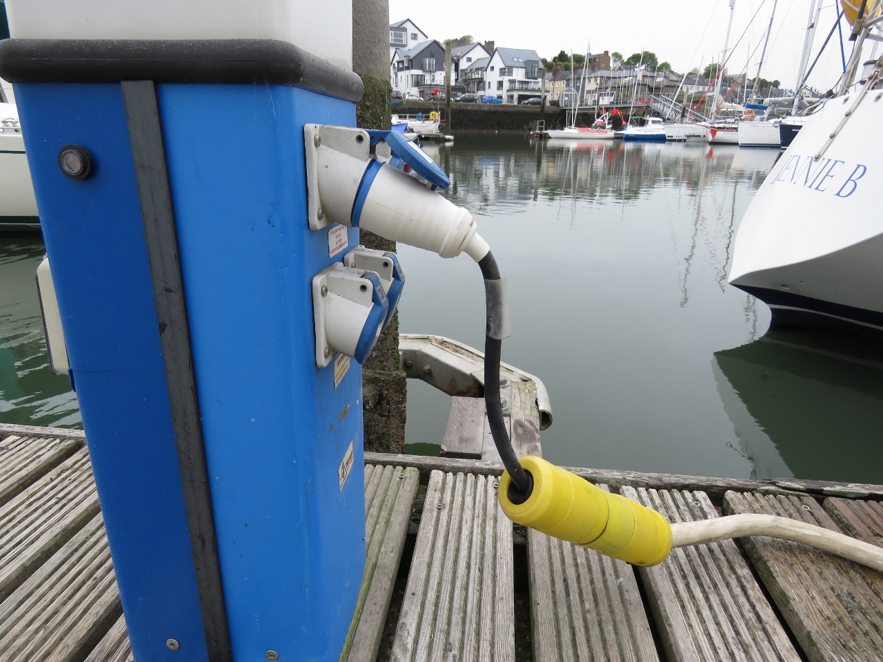
For the first several years of our trip around the world, we plugged into 16A/240V shore power by running our 50A/240V cable to a shore power pedestal, then using a small pigtail adapter to plug into the pedestal, as pictured below right in Kinsale, Ireland.
 |
 |
| Connecting to shorepower via pigtail in Kinsale, Ireland | |
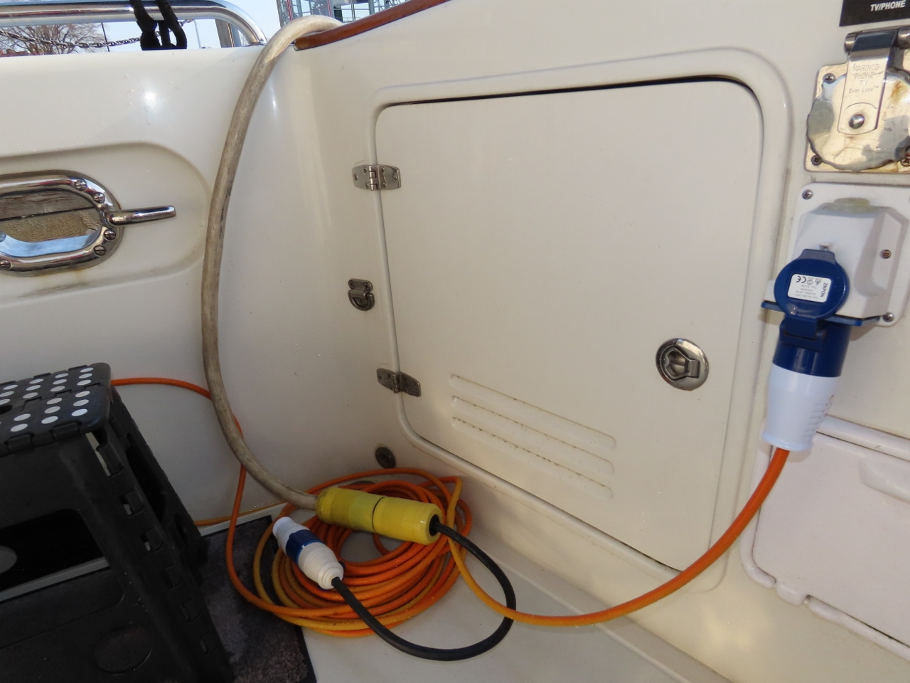
The 50A/240V cable and pigtail adapter solution worked well, but the cable is big and heavy to move around and we only have 140ft of that. In Europe we sometimes found the 140ft wasn’t enough. To mitigate this, we purchased multiple 16A/240V extension cords in the UK that give us 450ft of reach. Even two of those lightweight 16A cables are easier to put out than the bigger 50A cable. Unless the shorepower is very close to the boat or we are connecting to 32A/240V, we typically run the 50A/240V cable just into the cockpit, where we adapt it to a lightweight 16A/240V cable and run that to the shore power pedestal. This configuration is shown below in Bergen, Norway prior to the dual shorepower project. This approach also reduces the pigtail connection’s exposure to weather, so we are less likely to see issues due to water intrusion at the connection.

With the new shorepower connection in the cockpit, we take this further. If we are going to use only a single 16A shorepower connection, we can simply run a lightweight 16A extension cord directly from the boat to shore and skip the 50A cable and its adapting pigtail altogether.
The dual shorepower system has been an excellent addition to our world-cruising setup, and we’d definitely include this design again were we to own another boat with similar cruising goals in mind.
James,
Articles (or information) like this is what makes your site so incredibly interesting, whether a cruiser or not. It is filled with practical approaches to solving a plethora of more or less complication problems and situations.
Site is almost a “black hole” as there is so much of interest to take in!
I’ve said it before; massive thanks to Jennifer and you for taking the time to compile it all and keeping the information up and available.
Thanks for the feedback on the blogs. Exactly what we aim for.