On arriving into Nuku Hiva in the Marquesas Islands in 2013, the fuel temperature in our supply tank had climbed to 180F (82C). What was happening is the engine circulates about 50 gallons per hour and yet only burns a tiny fraction of that. Most of this fuel flows through the engine fuel system and back into the tank. The return fuel has flowed around the hot injectors, and this helps to cool them, but it also flows through passages in the cylinder head. By the time it’s heading back to the supply tank, the fuel temperature will be very close to the engine operating temperature.
This sounds dangerously hot, but our Deere 6068AFM75 specification has the maximum operating fuel temperature at 212F (100C) so, from a specification perspective, it’s less than the rated limit. However, the spec also says the “normal operation fuel temperature” is 104F (40C) and the rated power for the engine is also produced at 104F.
The engine will run fine on hotter fuel. The engine control unit (ECU) will adjust the fuel injection quantities to be correct based upon many factors including air and fuel temperature. Fuel hotter than 104F (the fuel temperature used when rating the engine) will slightly degrade maximum power output, but the reduction isn’t large and full-rated power output seldom is needed.
In addition to a slight reduction in engine power output, there is a larger impact on fuel lubricity. Hot fuel lubricates less well than cool fuel and this is a bigger concern than the slight reduction in power output. Many of the fuel system components including the fuel pump and injectors are lubricated by fuel flowing through the system. These components run at very tight tolerances and, over time, they wear to the point of needing to be replaced.
Because fuel system high pressure pumps and injectors are quite expensive and will last longer with better lubrication, some operators choose to use fuel lubricity additives. Many report these fuel additives work well but, with or without special additives, one of the best ways to improve the lubricity of diesel fuel is to keep the fuel temperature down.

Of course, when talking about reducing fuel system wear, there is no step more important than fuel filtration. On Dirona, all fuel has to first pass through a 25-micron filter, then a 2-micron filter, then a 10-micron filter, and then a final 2-micron filter. We cover the details behind the filtration strategy in Managing Fuel Quality, but the key takeaway is investing in clean fuel is by far the best strategy in reducing fuel system maintenance costs and improving fuel system component lifetime.
After good quality filtration, the next most important step to increase fuel system component lifetime is to improve fuel system lubricity. The least expensive way to improve fuel lubrication is to run cooler fuel. There are two primary approaches to maintaining lower fuel temperatures: 1) recirculate the return fuel from the engine back into the bulk tanks that on all boats are large and, on some boats, are against the hull where they are water-cooled, and 2) use a fuel cooler.
The recirculation approach is fairly effective and it’s hard to argue with the simplicity of the technique, but there are a couple of reasons why we chose not to run in this mode. On Dirona the main engine draws fuel from the supply fuel tank and the re-circulation approach would return it to one of the bulk tanks where the fuel would be cooled by the larger mass of fuel with a very large tank surface area to dissipate heat.
Doing only what we describe here runs the risk of overflowing the bulk tank, and it will drain the supply tank in an hour on our boat, since the engine is moving 50 gallons per hour. Both the overflow and the fast tank drain problem are easily avoided by opening the valve between the bulk tank being filled and the supply tank from which the main engine is drawing fuel. With this valve open the bulk tank will directly drain into the supply tank ensure it doesn’t overflow and the supply tank doesn’t drain. This is often called the gravity transfer approach.
The gravity transfer model is easy to manage, doesn’t require frequent pumping of fuel into the supply tanks, doesn’t require much thought, and has the side effect of cooling the fuel nicely. For many operators, this is their approach to fuel management and it does have many upsides but there are two reasons why we chose not to use it.

On Dirona, we use an alternative fuel management technique where we both draw from and recirculate fuel back to the same tank. This is often called the pump transfer approach. We use this approach for two primary reasons. The first is that all fuel in the supply tank has always been through a large 25 micron Racor FBO-10 bulk transfer filter. This means that if we ever take on poor quality fuel we can polish it in the bulk tanks and none of it will get to the supply tank used to feed the main engine unless it has passed through the high capacity fuel transfer filter.
The second reason we use this approach is that all fuel in flight is fuel at risk. In the gravity feed approach, the entire contents of the bulk and supply tanks are all connected. So, if there is a fuel filter leak or a fuel line chafes through, the entire bulk fuel supply contents could be lost. When using the pump transfer system, only the small supply tank fuel volume is lost. The bulk tanks remain sealed off and not at risk. Near shore, the loss of bulk fuel contents could dump more than a 1,000 gallons and be a serious environmental problem. But offshore the problems get even worse. The loss of the contents of the bulk fuel tank when crossing an ocean puts the boat at risk of being stranded without sufficient fuel to complete the trip.
We prefer to have the bulk fuel load safely sealed off and we think it’s advantageous to filter all fuel before it is transferred to the supply tanks. See Dirona fuel manifold and Managing Fuel Quality for more information on our fuel management strategy and the motivations behind our decisions. One downside of the approach we have taken, however, is that the fuel in the supply tank can get quite hot over long trips.
Fuel Cooler
We have looked at why we chose to use the Pump Transfer rather than Gravity Transfer method of fuel management. This gives us many advantages described in the previous section but the primary downside is we need to manage fuel temperature. Technically the engine will continue to operate with higher temperature fuel, but we prefer using cooler fuel for the additional lubrication it provides and the prolonged fuel system parts lifetime possible when using cooler fuel.
Another advantage of cooler fuel is that the entire supply tank has a fairly large surface area and it forms a hot radiator in the engine room. The heat contribution of the supply tank won’t be remotely close to that of the main engine but it is large and, when nearly as hot as the main engine, can be a substantial contributor to overall engine room heat.
For those that choose the pump transfer fuel management technique, either the fuel needs to be cooled or the operator needs to accept the higher temperature fuel and its negative impact on fuel lubricity and the contribution to engine room heat that comes from a large body if hot fuel. Our choice was to cool the fuel.
What are the downsides to fuel coolers? They are relatively simple devices but there really are no “simple devices” in boating. Almost any component brings some compromises along with the other positive attributes and fuel coolers are no different. Fuel coolers can leak and they can leak multiple ways. A cooler can leak cooling water which makes a mess but isn’t really a big deal. They can leak fuel, which is a bigger deal. With reasonable engine room checks these leaks should be caught early and aren’t really a significant risk, but they are worth avoiding.
Every boater needs to come up with their own levels of risk aversion and their own approaches to risk management. For us, the above fuel cooler leak risk are relatively minor and can be mitigated, and the advantage of cooler fuel wins out by a large margin. However, there is a nasty risk mode that we’re not comfortable with and, as a consequence, fuel cooler design and selection needs careful thought. This risk is that cooling water (salt water) leaks into the fuel system. The negative impact from bringing salt water into a fuel system could be very large and include blowing off fuel injector tips, rusting internal components, and even an inoperative engine.
We view the advantages of a fuel cooler are justified and, having had a cooler in use on Dirona for 4.5 years and 5,622 hours, we are really happy with the addition. But it is one that needs to be done with care, not only in the selection of the cooler but also in how its installed.
Fuel Cooler Selection
The best way to avoid these fault modes is to go with a premium quality cooler. We selected a nickel brazed Inconel cooler that is used commercially to cool highly corrosive chemicals. Our logic on this is the best way to avoid corrosion failure is to start with the best possible components and use a cooler that has a long track record of being used commercially in far more difficult operating conditions.
For a fuel cooler, we selected a Hydac S610-10-INC625-NI/G1 fuel cooler. The cooler is a brazed plate heat exchanger made from nickel brazed Inconel (Austenite nickle-chromium-based superalloy) that is designed for highly corrosive environments like warm salt water.
Fuel Cooler Installation
Having selected a cooler that is unlikely to fail and allow water to leak into the fuel system, we then want to choose an install technique that will detect water before damage is done. In effect we want to choose a cooler that won’t fail in the life of the boat and then want to install it in a way that will allow us to survive a water leak.
A common fuel cooler installation location is to cool fuel on the way to the engine. This approach has numerous downsides, some serious and some just annoying. The first is the fuel supply tank won’t be cooled in this approach and will remain a heat contributor to the engine room. This isn’t a huge factor but it is a consideration. The second issue is, with the cooler in the suction side of the fuel system, there is a greater risk of water being pulled into the fuel. The third and serious issue is that a water leak could result in water is being pulled directly into the engine and will quickly overwhelm the on-engine fuel filtration and water may make it past these filter before detection.

|

|
Our approach was to put the cooler on the fuel return line that heads back to the supply tank. This installation point has the advantage of cooling the engine heading to the supply tank, so it both cools the fuel heading to the engine but also the fuel in the supply tank is cooled. This will help the supply tank not contribute to heat load in the engine room.
Another advantage is the water is heading back to the relatively large supply tank. The supply tank has a water-in-fuel detector in the bottom of a sump below the fuel pickup. In this design, there will be a water-in-fuel alarm prior to the water level reaching the fuel pickup. The sump will hold about a half-gallon of water before it fills and the water reaches the pickup.
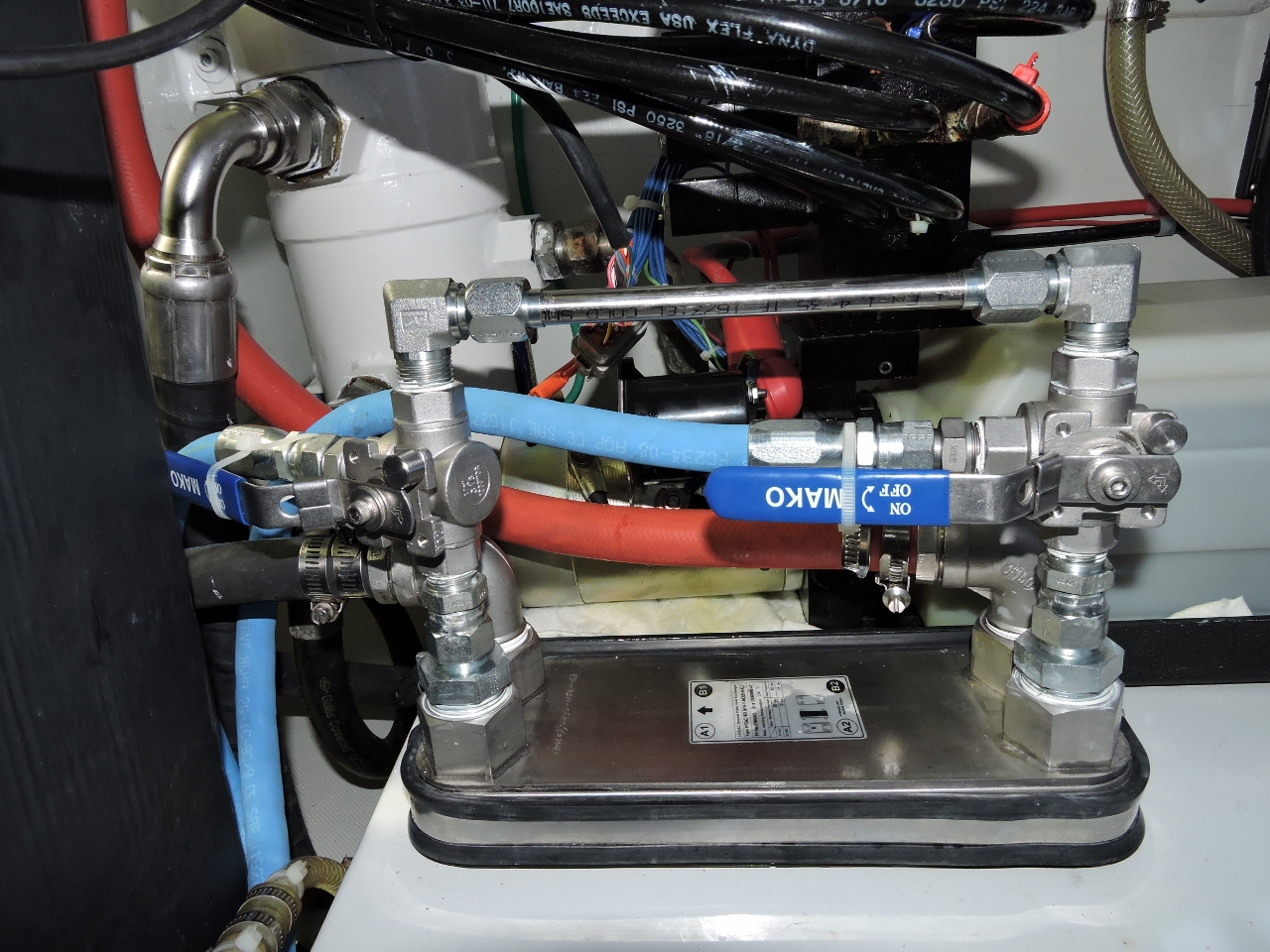
The pictures below show the supply tank sump (underneath the yellow handle in the first picture and at left in the second). The water-in-fuel detector is visible extending from the front of the sump in the first picture. Note the fuel pickups are well above the sump. Click either image for a larger view.


At this point, we have taken many steps to ensure we get the advantage of cooler fuel without the disadvantage of a failed fuel cooler. We started by choosing a cooler that is unlikely to leak. We then put the cooler in the fuel return line ensuring it flows first to a large sump where the fuel is draw off above and the sump has a water-in-fuel sensor. The next level of defense is the fuel flows through RACOR 900s with water drain bowl. The next level of defense is the 10-micron on-engine fuel filter also equipped with a water in fuel sense. The final level of defense is the 2- micron on-engine fuel filter before the fuel flows to the high pressure pump.
Conclusion
In this design we have cool fuel and have made the risk of fuel contamination from the cooler system remote. In nearly 4.5 years and 5,622 hours, the cooler has run without issue and shows no signs of corrosion, and we expect it will outlive the boat.
The best measure of value will be fuel system component life. In our world travels we get fuel of varying qualities so we rely heavily on our fuel filtration system. We now have 10,830 hours on the high pressure fuel pump and it continues to produce called-for pressure without issue and shows no signs of wear.
The fuel injectors ran for 9,522 hours before we replaced them, which is a pretty good lifetime for modern high-pressure, common rail injectors. And, since these injectors were used for the first 5200 hours of their life on high temperature, non-cooled fuel, it’ll be interesting to see how many hours the current set of injectors will go. We believe up over 12,000-15,000 hours for injector life is quite possible and that the risk of fuel cooler failure is low with the component and installation approaches we have chosen.
To further clarify, where did you mount the fuel cooler and is it affixed with any fasteners? Also, is your inlet water temperature around 130F? Did the location of the cooler depend upon the elevation/head pressure from the connection point of the water line?
Thanks in advance.
Yes, that cooler company supplies optional clamps that circle the cooler and can be used to attach it to a bulkhead. If you look at the picture in the second row from the bottom, you can see the cooler attachment to the tender crane hydraulic pump. Water that flows through the cooler has already flowed through the hydraulic cooler and it’s usually very near to water temperatures because the hydraulic system is usually not doing much. It only works hard anchor handling or when using the thrusters. And, even when it does work hard, the outlet water still isn’t much above ambient water temperature. Ideally every cooler would get it’s own coolant flow but, if you do combine, the hydraulics isn’t a bad choice since the flow in that raw water cooling system is adjustable.
You also asked about the cooler location. I put it at the hydraulic heat exchanger to avoid changing hydraulic cooling water flows much. The choice is to move the fuel a long distance or move the cooling water a long distance since the main engine and the hydraulic heat exchanger are a long way apart. I went with move the fuel and slightly prefer that approach but either would work fine.
Hi James,
Where in the water loop are you inserting the water side of the heat exchanger?
It’s after the hydraulic heat exchanger so has been through some preheat. But, i’m fine with the cooling water pre-heat since 130F is very hot for our hydraulics (we show a warning light there). The manufacturer does audible alarm at 160F and emergency shut down at 180F. This holds the fuel temp down quite low and is an easy post-build installation without more pumps to service.
Interesting write-up. I have fuel coolers on the Cummins 6BTA engines in my Bayliner 4788. They are plumbed into the fuel return line as you described and are cooled by the raw water directly after the engine’s raw water pump. Many other 4788 owners that live in the PNW have removed their fuel coolers as they are deemed unnecessary. Since I live in an area where water temperature is frequently north of 80F, I replaced mine last year as part of a larger engine heat exchanger project. It just didn’t seem a wise choice to have tanks of hot diesel just beneath the floor!
I understand your concern. Fuel flash point is the temperature at which vapors can ignite and, on diesel, it’s a fairly high 126F. Below this the fuel vapors won’t burn. The auto-ignition point is the temperature at which vapors start to burn without an ignition source. On diesel the auto-ignition point is a very high 493F so those large loads of fuel below are pretty safe even with higher diesel temperatures but, if you keep your fuel below 125F, you are even safer.
What was the fuel temperature decrease that was achieved by running the fuel through the fuel cooler?
Looking the year before and the year after at the tank temperatures when the engine was running the peak went down from 190 to 132F so the deltaT was reduced by 58F. The average went down from 132F to 102F for a reduction of 18F. The peak is a good measure of the reduction since the peak is measured after a long run and with less filled tanks where the cooler is contributing most whereas the average will be short runs where the cooler contribution is less.
I was curious as to why such a high circulation rate (50gph; 190Lph), or even why circulate in the first place. Doing a bit of digging: cooling.
“””
In a diesel engine, the fuel system is much more complex than the fuel system on a simple gasoline engine because the fuel serves two purposes. One purpose is obviously to supply the fuel to run the engine; the other is to act as a coolant to the injectors. To meet this second purpose, diesel fuel is kept continuously flowing through the engine’s fuel system at a flow rate much higher than required to simply run the engine, an example of a fuel flowpath is shown in Figure 17. The excess fuel is routed back to the fuel pump or the fuel storage tank depending on the application.
“””
* https://www.myodesie.com/wiki/index/returnEntry/id/3030#Fuel%20System
Learn something new everyday.
Exactly and the net impact of that is that there is a large quantify of fuel heading back to the tank that very close to engine operating temperature (180F to 200F).