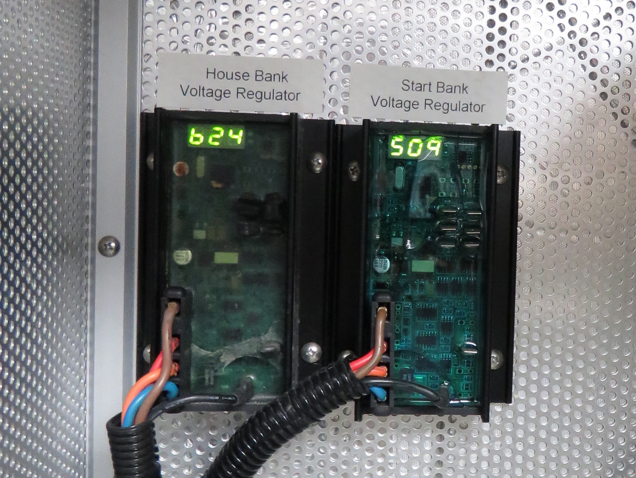
In our charging configuration, we parallel the house and start alternators to charge the house battery bank. Each alternator has its own individual Balmar Max Charge MC-624 regulator and we’ve been asked a few times if we balance the outputs using a product such as the Balmar Centerfielder. This is one of those issues where people work very hard to solve an apparent problem that really isn’t there. When running two alternators or two charging sources of any type, people notice that one is charging and the other one at times, hardly is charging or is not charging at all. This often is described as the alternators “fighting each other”, so people naturally want to fix the problem.
Let’s look at what is going on and then talk through why it’s really not a problem. Batteries go through three broad charging phases (Balmar divides it up into 12 stages but three phases is the level of detail we need for this). The first phase is bulk charging, where the regulators give a target voltage and the alternators produce as much current as they can (it’s just about impossible with AGMs to have so much charging capacity that you exceed the battery acceptance rate). During this phase, you get max alternator output current from both alternators until the target voltage is hit.
The next phase is acceptance. During this phase the voltage level is held constant and the amperage the batteries can accept slowly goes down until it gets down to around 1 or 2% of overall capacity, at which point they are considered charged and the system switches over to float mode.
It’s during this acceptance phase that many owners worry that the two alternators should be balanced. During this phase the batteries will accept (that’s the reason for the name) a certain amount of current. Initially it’ll be max charging system output, but this value falls continuously until the battery is charged.
As an example, if you have two 100A alternators and the batteries are accepting 80A, then most owners want to see each alternator producing 40A. But, they instead might see one producing 60A while the other produces 20A, or even 80A and 0A. It does seem like a problem but, if you think about it, the batteries are charging as fast as they would with a single 200A alternator, so the overall charging rate is fine. The only problem is one alternator is doing more work than the other.
“Who cares?” is the short answer, but it is worth looking deeper. With one alternator doing all the work, that alternator is spending much more time at 100% output so will get hotter and will wear more. This is harder on bearings and produces more heat. So there is some value in having something close to balanced output, but the value is pretty minimal. I put 4,100 hours on the previous boat with two alternators never worrying about it. And we have put on 7,800 on our current boat, again, just not worrying about it. I tune the two regulators such that they are “close enough” so that both alternators contribute something. Right now, I have one running at 158A and the other running at 64A. That’s perfectly fine from my perspective. Earlier tonight we had two air conditioners and the oven on and both alternators were running flat out — these alternators can do that for hours at a time so I don’t worry much about balance.
The important things to think about are: 1) two alternators won’t be balanced in production during the acceptance phase and it really doesn’t matter, 2) they are charging your battery bank as fast as a single alternator of the aggregate capacity of your two alternators, and 3) there is some (small) value in setting the two regulators close and this is easy to do with Balmar Max Charge system or any other fully tunable regulator.
The main headache with two charging sources is when they charge out of synch and one commences a bulk/absorption charge when the other alternator may have just completed and gone to lover float voltage. This means the batteries spend more time at 14..4V than they really need to with each absorption cycle taking up to two hours.. With Lifelines this issue is probably academic as to whether there is any shortening of lifespan, however with conventional lead acid (eg T105’s) the water consumption is higher than it needs to be and risks of running dry are increased. The more transient the charging cycles the worse the issue gets.
This is not an issue of chargers fighting each other, more a problem of minimizing time spend on absorption. I think the worst case is larger capacity solar or wind systems trying to charge alongside a genset. Each time the wind picks up , another absoprtion cycle is triggered!. An engine and a genset on the same bank run once a day?…probably not so much of a problem.
Very frequent returning to bulk can be a real problem in that higher voltages are not good for batteries. The best way to defend againts it is to first ensure that the bulk levels are below the battery manufacturer temperature corrected limits (Lifeline in our case). After that, the next step is for us to dig deeper and understand what causes charging system to enter bulk charging and think through each and figure out if it matters whether or not both are in bulk at the same time.
I’ve grouped the causes of re-entering bulk into 3 groups: 1) charging component was just turned on, 2) battery voltage when down below the “return to bulk” voltage, and 3) most chargers periodically re-enter bulk charging.
On #3 it’s an event that is hours to days apart and, if you are unhappy about the frequency, you can often adjust it to longer. It is true that these re-enter bulk periods caused by fixed timing might be doubled when using two chargers (if they don’t have the same timing or weren’t started at the same time) but these are sufficiently rare that I don’t view them as material in the life of a battery.
#1 is much the same. When a charging component is turned on, it will briefly enter bulk before transitioning back to absorption then float. Turning charging components on should be an unusual event. In the example you gave where wind is becoming available and then stopping repeatedly, you will enter bulk frequently. This isn’t really a two charger problem but a wind problem since it would happen if you were ONLY charging with wind. To mitigate the impacts of this one, adjust “min bulk” to something super short like 10 minuntes to avoid any issue from this one.
#2 is more interesting since it can happen fairly frequently. When a large load hits the bank especially large loads that near charger capacity, the battery voltage will drop and the charging system will transition back to bulk to pass through anouther charge cycle. In this situation, that is exactly what you want but what if only one chargers makes the transition?
It doesn’t matter since one of two outcomes will follow:1) the single charge source completes the cycle successfully, or 2) it lacks the resources to complete successfully and the other charger then makes the transition to bulk as well. In the first case, the right thing happens from a battery perspective so no need to worry. In the second case, the right thing happens from a battery perspective and the only issue is the second chargers didn’t transition immediately which won’t impact battery life.
James, I was using this post as part of a follow-up in my Marine Electrical class – great stuff, and thanks for the engine injector feedback.
Unless it’s just the photo, the house voltage regulator potting epoxy appears to be in tough shape? I know you carry a spare and it has 1000’s of hours of use, but the start VR appears to look like new.
Good eye Michael. Yes, that cracking in the epoxy potting happened very early in the life of that regulator. It doesn’t seem to impact it’s longevity although it takes it from virtually impervious to water by design to probably not being able to survive direct contact at this point. The start regulator had a related issue where it some cracking as well. It eventually failed due to completely loss of the firmware. I wasn’t able to reprogram is so replaced it.
James,
Thanks once again for your insightful post, electrickery was never my strong suit and I have learnt more following your efforts, particularly that long one on the why and where’s of Dirona system than all they tech courses I have attended over many years in aviation. The only “control” we have in the cockpit are CBs, that are either on or off and beyond that a tripped one is usually cause for much reflection on what may be behind it prior to resetting. ???
Our approach is to accept complexity in design or installation in order to get simplicity in use. The risk with more complex systems is that, if not done right, they fail more frequently. The goal in all we do is simpler to use, less likely to see user error faults, more redundancy, and less service.
“Close enough!”
Even though it doesn’t initially looks like an expression you’d be using, I must say I totally agree with your reasoning and MO!
Never had to worry about that on my Contessa , since there was only **one** alternator on board (-; but that’s one more for the “how to” file for the future!
Good hearing from you Jacques. We hope to see you when we get to Europe.
You mentioned that you had the engine running. Was the writing of this post prior to arrival in Florida?
Careful reading as usual Timothy. I think I wrote the note before Barbados but I’m not sure. Deffinitely it’s been a while. I often save a blog or two for periods when I’m busy with other things.
I cannot tell you how much I enjoy these posts. I learn something new every time! I am of the mindset that I would rather carry a spare alternator than create a whole system to balance them. The dual alternators to the battery bank and then using the inverters for AC power is a great way to run the boat. I am not a fan of generator use, unless large amounts of power are required, so the system you have on Dirona is great and is a model for me. Someday when we get the N40 I will ask you for a wiring diagram and parts list so I can do the same. Heck, you probably have enough to publish a book ;-)
Yes, it’ll come as no suprise to you that, as well as the two installed alternators we also have a spare alternator and regulator :-). I’m sure all of the systems we have evolved on Dirona could be improved upon but, sure, we are happy to share the details behind any of them.