.jpg "Beveridge Reef, South Pacific")
A little over a year ago, we worked our way south from Fanning Island, Kiribati towards Nuku Hiva in the Marquesas Islands. We were on a long, fuel-constrained run where we would cover 2,600 nm without fueling. For most of the trip, we were heading up-current and into 30 kts of wind on the bow. The waves were fairly well-developed and spray filled the air day after day. The outside temperature was well over 80F, and the master stateroom was 88F, which made sleeping more difficult. With the doors open for ventilation, a thin layer of airborne salt soon covered the boat interior. But we were not crazy about closing the boat up and running the air-conditioning, because that consumes more fuel and would be a couple of weeks of generator run time at very low load.
As we neared Nuku Hiva, we concluded that we had far more fuel than we were going to use, so we might as well be comfortable and run the air conditioning. I’m not crazy about extended run times on the generator at under 20% load, but it’ll live with it, and it was so wonderful and relaxing to finish the last few days of the crossing sleeping well in air-conditioned comfort. This convinced us we needed to find a way to air-condition the boat underway without running the generator.
In the Tuamotus, we were diving daily and just loving it. It’s just amazing to look up from 140′ down and be able to clearly make out our dinghy floating above us and then look down and see 150′ down to the ocean floor and be surrounded by beautiful fish, sharks swimming by, and a sea turtle making a pass through the area. It was incredibly beautiful, but we found ourselves wondering what would happen if our generator failed. Without the generator, we can’t fill SCUBA tanks, can’t make water, and can’t use the washer, dryer or oven. The inability to make water when that far “out there” is not at all appealing. Our goal is to never have a trip ended early or be redirected by a fault and it would be very difficult to get generator parts flown into some of the obscure, uninhabited islands we visited on this trip. We needed a backup to the generator, but really have no space for another generator on Dirona.
 (1280x960).jpg "Anse Amyot, Tuamotus")
As we continued across the South Pacific we spent the vast majority of the time on anchor. But when we did go to a marina, the shore power was rarely better than 15A. Some of those 15A connections could only reliably deliver 12A without the breaker triggering, and in some places the shore power capacity was over-taxed by the visiting boats and, consequently was sagging badly. Also, they were often 50-cycle connections and Dirona is a 60hz boat, so we couldn’t run most 240v appliances without running the generator. We really felt we needed some way to draw what the shore power had to offer, but to not trigger a breaker and not have to manage the boat to a consumption of less than 15A. Both Atlas and ASEA offer shore power frequency converters that would handle the cycle difference, but they are expensive—friends have spent as much as $50,000 on shore power conversions—and they still don’t allow running the boat well at over 25A while drawing under 15A on the shore power connection. The frequency converters didn’t look like a good solution for the entire problem.
.jpg "Med-moored in Papeete")
After many nights of thinking through options on passage, and planning and drawing up different solutions during the day, we came up with a solution that appears to solve all the problems outlined above. We installed the new design when we arrived in Whangarei, New Zealand and, having used it for the last year, it really does seem to nail every requirement listed above and a few more. Summarizing what the system delivers:
Backup generator: If our generator fails, we need to be able to operate all 240V appliances including the water maker and SCUBA compressor and produce up to 8kw of power, without installing a second generator. This is super important were the main generator to fail (it never has), and is also very useful for quick 240V loads like running the oven for 10 min without bothering to start the generator.
Efficient light 240v loads: Light 240v loads, such as running a single HVAC while underway, is not an efficient use of the generator. While light loads generally aren’t ideal, our bigger concern is that running the generator 24×7 increases the maintenance frequency. Changing the oil and filter every 10 days is not where we want to be.
50hz/60hz invariant: We have a 60 Hz boat, but more often than not are plugged into 50Hz power. We needed to be able to connect to 50hz or 60hz and run all appliances without restriction and not have to start the generator.
Very low amperage shore power invariant: We want to be able run all appliances regardless of draw without any restriction, without having to run the generator, and with only a single shore power connection that might be as small as 10A at 240V or 20A at 120V. Boats are getting bigger and better equipped all the time and many marina shore power systems are not up to the draw they are asked to deliver. It’s not unusual to see shore power voltage drop down 20% below nominal line voltages. Voltage sags can damage equipment, so we needed isolation ensure that our equipment gets clean, voltage stable power even when the shore-side system is sagging under the collective load.
110v failover: If the 110v inverter fails and we’re not connected to 60hz shore power, we must start the generator to get 110v power. We wanted a backup for a 110v inverter failure without plugging in or starting the generator.
Battery protection for shore power loss: A big concern when leaving a boat unattended at a marina is the shore power could get disconnected, unplugged, the breaker may trip, or a variety of other mishaps could leave the boat unpowered and drain the house batteries. This is bad for the batteries and might result in other problems such as spoiled freezer food. We want the system to ride through a shore power fault by failing over to the generator, running it if needed to save the batteries, and return automatically to shore power if it comes back.
I’ll start with the equipment we installed and how the different components work together to solve the requirements we have itemized above.
1) Install 240V, 60Hz Inverter: This is the most important part of the design. Install a sufficiently large inverter system such that all appliances in the boat can be run off the inverter. On Dirona, we have a 4kw inverter to feed the 110V appliances, so 6kw is sufficient to support the 240V equipment we have on board. In our case, we installed 2 paralleled Victron 3kw 110V inverters to achieve 6kw of 240V power. We particularly like this inverter choice because they are simple and don’t include a charger—all they can do is invert—and are capable of delivering far more than their specification. The inverters are specified to deliver 6kw at 240V, which is roughly 25A, but they can deliver peak loads over 50A and can operate for extended periods at or even beyond their rated output without sag, over-temperature, or cutting out. They are tanks, and just keep delivering no matter what. I’m amazed to report they can start the SCUBA compressor, where the required inrush current at startup can exceed 50A. After a year of use, we just love these units. The key to making this design work is to ensure that the inverter capacity is sufficient to run the boat without restriction, using whatever combination of 240v equipment you need. So, if you chose to duplicate this design, ensure you have adequate inverter capacity. 6kw is enough for us but you can get 240V inverters in a variety of sizes up to 20kw. And if your boat is 60hz, you’ll need a 240-volt split-phase inverter–some appliances need that neutral connection.
.jpg) |
.jpg) |
.jpg) |
.jpg) |
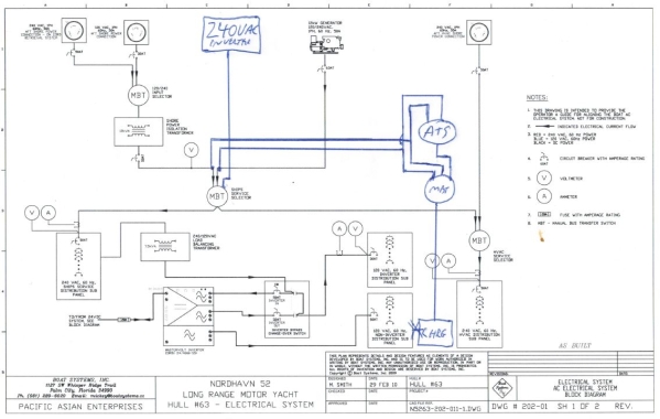
2) Upgrade Ships Service Selector Switch: The Ships Service Selector switch as delivered on Dirona (leftmost of the three in the first picture below) allows the operator to feed the 240V breaker panel from either shore power or the generator. We replaced this switch with one supporting a 3rd input (2nd from left in the second picture below) so we can feed the 240V panel and all 240V appliances on the boat from 1) shore, 2) generator, or 3) inverter. This third position runs the entire house system off the new 240V inverter.
.jpg) |
.jpg) |
3) Install Battery Charger Selector Switch: As delivered, the battery chargers on Dirona draw power from the 240v panel. In other words, one of the 240V “appliances” are the two battery chargers. It would be a very bad configuration indeed to be running the 240V appliances off the inverter and have the battery chargers taking power from the inverter, using it to charge the batteries, which are then feeding the inverter. To support many of the use cases above, the chargers must be powered separately from the 240V panel. We want, for example, the 240V panel to be running off the inverter while the chargers are running off shore power. So we separated the battery chargers from the 240v panel and added a Charger Service Switch (leftmost of the four in the second picture above) to supply the chargers from either shore power or the generator.
An electrical diagram showing these first three modifications is below.
4) Upgrade Start Battery Alternator: The final component upgrade to complete the system is replacing the 85A start battery charger with a 190A @ 24V alternator and installing heavier cabling for this larger alternator. The house battery bank already has a 190A @ 24V alternator so, in this new configuration, we have two 190A @ 24V alternators on the main engine. With the two alternators in aggregate, we have 9kw of power generation on the main engine. But, you probably wonder why we would ever want a 190A charger on the start battery system. The original 85A alternator was arguably already far more than would ever be required. Well, it turns out that bigger is not really a problem in that a large alternator with a high quality smart regulator can produce whatever the start batteries need regardless of how low. So, having an extra-large alternator does no harm but is unnecessary. When this second large alternator becomes very useful is when we parallel the house and start alternators onto the house battery bank. In that configuration, we can produce over 9kw of charging for the house battery bank. In our standard configuration, with only a single house battery bank alternator, we have 4.5 kw of power available all the time. We can run air conditioning units, the water maker, and charge the batteries. If we need more power, we can parallel in the start alternator and have 9kw available. This is useful if we have a generator failure but there are times when it’s nice to be able to charge the batteries at 300A for an extra fast charge and still be able to run the water maker or air conditioning system.
.jpg) |
.jpg) |
To make it easy to parallel in the start alternator when needed, we mounted a switch and warning light on the dash that closes a 200A continuous duty relay to make the second alternator available to supply the load when needed by just flipping a switch.
.jpg) |
.jpg) |
With these four sets of new components and changes installed, we can solve all the problems we outlined above by combining these components in different ways. Repeating the requirements list above, we’ll see how each is solved.
Backup generator: The combination of the 6kw 240V inverter and the 9kw of main engine charging capability allows us to have a backup generator without giving up the space. Generators are reliable and we have never experienced a disabling fault, so it’s hard to justify giving up the space for a second generator in a small boat. If we do end up needing the backup, the hours on our main will go up marginally, but the trip will be saved. It’s nice to not give up space for a second generator and yet still have the redundancy protection that comes from one.
Efficient light 240v loads: There are times when you’d like to run the oven for just 10 minutes, but it’s just not worth starting the generator for such a short period. The 240V inverter is happy to deliver the power and although the battery draw is high, it’s short enough that it doesn’t really consume that much power. It’s a nice efficient way to deliver the power for short periods without having to start the generator. Another usage model is low loads when underway. A single air conditioning unit draws less than 8A. It’s not worth having the generator on 24×7 and having to change the oil every 10 days if you only need a small amount of power. The combination of the 6kw 240V inverter and the large on-engine alternators allows even fairly large 240V loads to be run any time without needing to start the generator.
50hz/60hz invariant: The combination of #1 (install 240V inverter), #2 (upgraded Ships Service Selector switch), and #3 (new Charger Service Selector switch) allows the boat to be run entirely on the 60hz inverter, while dual redundant 100A @ 24V Mastervolt ChargeMaster 24/100s charge the batteries. The Mastervolt chargers will run happily on either 50 cycle 60 cycles, so the batteries stay fully charged even on 50 cycle power while the boat continues to operate at full capability as a 60hz system. We never need to start the generator to use the oven or laundry for example. The combination of the chargers and the inverter can run any appliance at any time.
Very low amperage shore power invariant: Extending on the 50hz/60hz invariant point above, we can run on shore power connections as low as 10A at 240V or 15A at 110V even though our peak draw is often nearing 30A at 240V. Because the shore power is charging the batteries and the inverter is powering the house, instead of needing the shore power to provide the peak power requirements of the boat, we only need the average requirements. Often when a hair drier comes on and, say the water heater is already on, the sudden additional 8A draw will cause the shore power breaker to disengage. This is because the shore power is insufficient to meet the peak requirements of the boat. But, if running using the battery charger and inverter pair, as little as 10A is enough to power the boat even though our draws are often approaching 30A. Shore power only needs to supply average power draws rather than peaks. It’s amazing what a relief it is to not have to manage loads, worry about what is running when, and not have to go out and reset the breaker multiple times each day. Suddenly shore power “just works.” And there will be times when old shore power breakers can’t deliver their rated output. I’ve often seen 16A breakers that will pop at anything over 12A. That’s fine too. We just set the charger draw to what is available on shore and forget about it, knowing we will take what we need but never more than the shore power system can provide.
Shore sag invariant: The 240V power systems in many US and Canadian marinas is actually 208V. And, when overloaded the “240” can sag down below 200V, which can damage electrical appliances. With the combination of a 240V inverter powering the house and only the battery chargers connected to shore power, the boat always sees rock solid 240V power through the inverter, while the battery chargers deal with voltage sags and other shore power problems. The Mastervolt chargers will charge on just about any voltage and frequency in the world, so it all works without exposing the boat systems to sags, spikes and other shore power related anomalies.
110v failover: Our boat has both a 240V system and 110V system. The 110V system has a 4kw inverter and, if it fails, the only way to get 110V is to plug into 100v, 60Hz shore power or start the generator. With the 240V inverter, we can still get 110V anytime without running the generator via the 240V inverter. It feeds single phase 240V to the 240V system just as the generator would and the Nordhavn standard step down transformer will just keep producing nice, clean 110V output even if the 110V inverter fails. You might ask why bother with the 110V inverter at all? It could be eliminated without giving up any advantage described here but a larger 240V inverter would be required if we gave up the 4kw of 110V inverter. If we were doing a new build today, we probably would opt for a larger 240V inverter and omit the 110V inverter entirely.
Battery protection for shore power loss: Our battery selector switch (#3 above) has 3 input options: 1) shore, 2) generator, and 3) auto. Auto is an interesting configuration. In this mode, a large 120A continuously-rated relay is used to select between shore power and the generator. If shore power is available, the battery chargers are run from the shore power system. If the shore power system fails, is unplugged, a breaker pops or any other fault causes a loss of shore power, then this relay switches the battery charger source to generator.
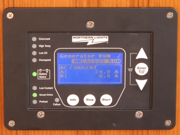
Since the generator is not running, you might wonder what value there is in switching to the generator. Dirona is equipped with generator auto-start so, if the batteries are discharged to 50% capacity, the generator starts, the load is brought on after 2 minute warm-up, it charges the batteries back up, the load is removed for 1 min of cool down, and then the generator shuts off again. The auto-start system is a simple extension of the Northern Lights Wavenet system. The normal use of auto-start is to take care of the batteries and ensure they get charged when needed rather than when I remember. Jennifer and I are often late getting back to the boat after shore-side exploring. Rather than allow the batteries to discharge excessively, shortening their life, the generator just turns on and gets the job done without attention. Auto-start is a personal decision where each owner needs to weigh off the risk of running a generator without attention against the risk of allowing the batteries to discharge. Our take is well-maintained equipment works well and, just as most people wouldn’t think twice of having their furnace kick on to prevent frozen pipes when they are not at home, we think auto-start is good for the boat. Even if you don’t decide to install auto-start, the Northern Lights Wavenet system is strongly recommended. We love it.
%20(600x451).jpg "Med-moored in Papeete")
The combination of the “auto” position on the Charger Selector Switch with generator auto-start/stop means that if something goes wrong with the shore power, the generator will start a day or so later, charge the batteries up, and then shut down and wait for when needed again. If the shore power comes back, it switches back to shore power and uses it again. We will also get email notification if the shore power gets disconnected and there are on-board alarms that signal this event but it’s still good to have backup to protect the nearly $8,000 worth of batteries.
Even if we weren’t cruising in 50hz countries, or remotely, where a generator failure would be difficult to deal with, we’d still install a 240v inverter. In fact, we’ve become so dependent on the system that we’re considering getting a spare. In the past, we needed to run the generator underway or at anchor to make water, do laundry or for baking. We now only run the generator at anchor, either to charge the batteries or for extended large 240v loads. The 240v inverter and either shore power or the main engine can handle the rest. A shore power connection anywhere in the world is now effectively the same as if we were in the US, with the added advantage of isolation from low or sagging supplies. And having air conditioning while underway in hot weather is wonderful.
Great set up with multiple redundancies. Well worth imitating.
A couple of questions… are those alternators rated at 190A constant load? Any problems with overheating when running at constant high outputs? Drive belt issues when running at constant high outputs?
You didn’t say, but I assume the batteries a lead acid variant? If so, how are they coping with high amperage charge and discharge? Lithium may do well here but with its own complication and risks.
Best Wishes,
The alternators do deliver 190A continuously. My approach in the past has been to limit alternator output to hold them below 225F to 250F but, as experiment on these Balmar alternators, I let them run at full output and the field temperature does go up to 300F to 315F but the alternators are absolute tanks and can do do this for hours at a time. AT that temperature full output decreases from 190A to 177A but that is still an amazing 4.2KW. I have no idea how they do it but we just ran them flat out and, when doing the laundry, they will stay at high output for many hours.
The Balmar 97EHD-190-24 are absolute tanks and seem able to run at full output indefinitely.
Lithium would be a good choice but the system was designed back in 2010 and so we built it on Lifeline AGMs. We considered changing to Li-ion but it’s a big project and we get great pricing on AGMs so it just never penciled out as a win.
Hi James
Can you give me the time/current/voltage configuration you use on the Mastervolt chargers to manage the charge profile? I’ve got my chargers on line but they are spending way too much time in Absorption mode, and putting excessive voltage and current into the battery. The batteries are getting hot! I just took them off line to cool them down, running purely on battery chargers now.
I did a first pass on the config a few mins ago, set the max absorption time down to 60 mins, and the return to bulk time to 240 seconds (I think that’s as high as it can go).
Thanks!
Chris
Hi James,
I just got the first of my Victron 24/3000 inverters installed. It’s running great now but first day was super frustrating. I discovered that the inverter will not start if there is a VE.Bus control panel plugged into it and the control panel is not powered. To me this is an incredibly poor design choice by Victron (also not documented, as far as I can tell). The inverter itself gives zero indication; it’s lights out, DOA, toes-up, pick your metaphor. I was ready to box it up and claim a warranty replacement.
I can imagine one possible rationale for this but it just seems stupid. I’m wondering what your thoughts are on that since we are both big fans of Victron (although they’ve gone down a notch or two for me now) and you being an architect of some extremely large scale fault-tolerant systems.
-cb
PS – the second Mastervolt charger is in, both chargers now on the house bus, with a third smaller charger taking care of the forward thruster battery.
Excllent, we’ve had pretty good service from our Mastervolt chargers over the last decade. My only criticism is they derate at 195V and I wish it was 5V to perhaps 10V lower. Some marinas have amazing voltage drop. Stockholm is nominal 230V but is often down in the 190/!95V range when under high load. We saw much the same in Capetown in the afternoons. I also run some very long power connections with not particularly large conductors which will have some voltage drop as well.
It doesn’t sound great but let me check on one thing. With my Victron remote, it’s off unless it’s plugged into the bus in which case it’s enabled. The off/on switch on the remote panel is turn the inverter(s) off/on rather than the panel. It’s always on. If that’s what you are seeing, that sounds like a reasonable design choice. Like you, I’m dead against a remote monitoring panel being able to disable a system but, if it’s a remote monitoring and off/on panel, you are kind of stuck giving it control of off/on. I like having the remote panel to be able to turn the inverter off and on since we don’t leave ours on all the time if we aren’t using 240V appliances.
If you hate that possible outage point, you can ditch the remote panel and the risk is gone but it’s useful in my view to be able to turn off/on. I don’t know of a remote Victron panel that isn’t also capable of turning off the inverter.
Hi James,
It’s the Color Control GX panel in this case, which is a purely digital gadget networked to the inverter on Victron’s “VE.Bus” connection. This panel cannot receive power from the bus (at least not from the inverter on the bus) and must be separately powered. That alone is kind of a sad state of affairs compared to Mastervolt’s MasterBus which powers their panels from the chargers or other main units you have on it. In any case this GX remote panel can certainly do on/off control as well as numerous configuration and monitoring functions but it does not utilize the completely separate remote on/off function which is really just a switch or relay wired to a jumper position on the inverter’s logic board.
So if the GX panel and the inverter are connected together, and the panel is not powered, switching the main on/off rocker switch on the inverter from off to on does nothing. Not even a blink on the leds. If you leave the switch in the on position and then apply power to the panel, the inverter powers up. If you then remove power from the panel, the inverter remains running. Switch the inverter off again, and then on again, and once again nothing.
I’m not willing to give up the panel (same reasons as you) but to me this is a giant banana peel in the middle of the sidewalk. A panel that is not powered should not alter the behavior of the system as compared to a panel that is physically disconnected.
I think Victron’s design approach is that the panel, when it is in system (even unpowered) owns control of the on/off state of the system. They pretty much say this, but not really explicitly, in the inverter booklet.
Which Victron remote panel do you use?
-cb
Oh, I just saw the photo of your Phoenix Remote with an actual physical on/off switch. So that’s just a remote version of the physical switch and leds on the inverter itself. Way different than mine, and with yours I can understand the whole remote on/off thing, but…
Exactly. It’s a simple off/on with LED overload, off/on, and bus connectivity reporting.
I agree that was a poor design choice for them. You might be able to have a simple congtroler like the one I use (Pheonix) that is bus powered on the bus at the same time where the simple bus powered controller sends the on signal. They might not allow more than one on the bus at a time but it’s a cheap check.
You may be able to experiment a bit and find a work around. Does unplugging the bus connection when the remote panel is depowered allow the inverter to start? If so, put a relay into the bus signal lines to interrupt when the panel is depowered. You might be able to add a second simple panel like my Phoenix panel to take over when the main panel is disconnected. If you can’t have two panels at the same time, you could put two relays into the bus connections for each and allow only one on the bus at the same time. Overall the design choice sucks but the gear is, overall, quite good. I suspect the simplest answer in this is to just accept that risk point and ensure it gets reliable power that is unlikely to be interrupted.
I just found this in the manual for the Color Control GX panel I’m using with the inverter:
“If you power the CCGX from an AC adaptor connected to the AC-out port of any VE.Bus product (Inverter, Multi or Quattro), then a deadlock will occur after the VE.Bus products are powered-down for any reason (after any operational fault or during a black start). The VE.Bus devices will not boot-up until the CCGX has power …but the CCGX will not boot-up until it has power. This deadlock can be rectified by briefly unplugging the CCGX VE.Bus cable at which point you will observe the VE.Bus products will immediately begin to boot-up.
Or a modification can be done to the RJ45 cabling. See FAQ Q21 for more information about this.”
link to the FAQ page: https://www.victronenergy.com/live/ccgx:ccgx_faq
It’s actually Q20, not Q21, but here is the relevant info: “Cutting/Removing pin 7 of the VE.Bus cable to the CCGX (brown/white according to standard RJ45 ethernet cable colour coding) allows the VE.Bus products to start up without waiting for the CCGX to boot up first.”
But Q21 is quite interesting also:
“Q21: I love Linux, programming, Victron and the Color Control GX. Can I do more?
Yes you can! We intend to release almost all code as open source, but we are not that far yet. What we can offer today is that many parts of the software are in script or other non-precompiled languages, such as Python and QML, and therefore available on your Color Control GX and easy to change. Root password and more information is available here.”
and here is the link: https://www.victronenergy.com/live/open_source:start
-cb
Good research Chris: “Cutting/Removing pin 7 of the VE.Bus cable to the CCGX (brown/white according to standard RJ45 ethernet cable colour coding) allows the VE.Bus products to start up without waiting for the CCGX to boot up first.”
I’m both a big Mastervolt and Victron fan but what makes Victron #1 in my eyes is this one: “We intend to release almost all code as open source, but we are not that far yet. What we can offer today is that many parts of the software are in script or other non-precompiled languages, such as Python and QML, and therefore available on your Color Control GX and easy to change. Root password and more information is available here.” That commitment to open source means that, even if they get it wrong, it can be worked around.
Thanks for posting what you have learned Chris. It’s super interesting.
Thanks James… That Q21 has “James Hamilton” written all over it!
-cb
It’s true. It’s like the Victron team wrote that one for me. It’s great to see them continuing to open source and/or provide APIs to their equipment.
BTW how do you keep your lazarette cool? I’ve got the two chargers and one inverter in there now and the air temp ranges 95 – 100F. Exhaust air from the inverter regularly hits 104 which puts the 3KVA inverter into max derate giving me only about 2200KVA, which is really not enough to run the 120 side of the boat. This inverter barely tolerates having the microwave on. I had to shut off the 120V domestic water pressure pump and use the 24V backup to avoid having the inverter completely shut down a couple times every day. As it is it’s still throwing overload events into log on a regular basis. I’d like to add some active ventilation to the laz because lowering the temperature will be better for everything but on the other hand the inverter’s lack of performance is really disappointing when I look at other manufacturers offering full rated power at 40C/104F.
Nordhavn was super worried about all the chargers and inverters in there and felt it would overheat but it’s not been much of a problem. Possibly because it’s a large volume space. It does run warmer but I mostly don’t care. For example, outside temps are 58 and and the Laz is 74. In the tropics, it ran in the 100F range and sometimes as high as 110F but I didn’t like wasting power to run the fans full time.
The inverter issue is actually a seperate issue or I convinced myself it was. In 75F ambiant, our Mastervolt Mascombin would overheat as low as 26 to 28A on a 33A system. When the laz is cooler, the same thing happened just slightly slower. I played around a bit but eventually concluded that Mastervolt had done a pathethetic job of cooling the inverter so the time at higher loads is really bounded. Cooling the laz helps a bit but it really only adds 5 or 10 seconds. The heat goes up very quickly in an inverter and it’s the poor mechanical design that was causing the heat problem.
You can see why Mastervolt did this. They want to make 100% sure that there is no water ingress even though customers put inverters in places that aren’t sufficiently protected from drips. The Mastervolt airflow design is up from the bottom and then out downward facing vents along the side. This has new unfortunate characteristics. First since the air is venting out the side, components near the top are getting close to no air flow. Second, the side vents are aimed down and not that wide so quite restrictive in the flow.
So, given my choice of cooling the laz or living with the laz and cooling the inverter better, I went for the latter. Since we don’t drip water on my inverter,I cut two large 3″ holes in the top of the case and put two big air movers on each. When the inverter draw goes up over 17A (on a 33A system) I turn on the 2 exhaust fans on the top of the inverter which moves a lot of air and the system instantly got super solid. It can hold 33A and it can hold it for a long time. The airflow made massive difference. And, even though the laz is still hot, if you move enough air, it still cools fine. The deltaT between the component temps in the inverter and the laz ambiant is very high at 70F ambiant but it’s still pretty high at 100F.
The cooling system works great. Since I’m turning the inverter fans on based upon inverter load, I used the same signal to turn on the 2 laz blowers and so we get some air moved in the laz as well. I think the positive impact of the latter change is small. The new inverter cooling system made a massive difference. Check out Hot Rodding the Mastervolt Cooling System: https://mvdirona.com/2016/02/hot-rodding-the-mastervolt-inverter/.
P.S. the 240V Victron inverters (dual Phoenix 3000) are mounted on an aluminum plate in the center of the laz and between them having a more efficient cooling system and them being in the center of the space, they never overheat and are fun running full load 25A @ 240V for a long time and I’ve seen the 6kw system as high as 7.5kw for short blips.
I remember the MasterVolt cooling project quite well. I’m sure my Victron inverter would benefit from the same approach. It’s the same inverter that you have two of so I’m not clear on why I’m having what looks like temperature related performance problems when you are running fine, other than the obvious difference of you being in a climate of at least 30 degrees F cooler than mine here in NC. My inverter is doing exactly what the documentation says it will do at the temperatures I’m seeing. It’s hard to believe you had acceptable performance on these inverters when you were in the tropics. I have to get the temperature down so that I really have a 3K inverter, or I will need to buy inverters that will not derate. I agree with you on localized active cooling rather than trying to cool the entire space. Makes a lot more sense thermally speaking.
Also, my Victron inverter is not ideally situated; it’s in a temporary mounting in a non-ideal location which I plan to improve on when I have access to some more construction materials. I don’t have room behind my rudder post as you did (looks like a tough spot even on your larger boat) but I can definitely get the thing more out in the open.
It’s interesting your are having trouble with yours. We’ve even used them to run the scuba compressor in tropics and the inrush on that single phase motor is crazy high. How hot is your laz right now? We seemed to do fine in the 100F range with no cooling changes on the Phoenix 3000. You can see the mounting location of ours in this blog: https://mvdirona.com/2014/08/a-more-flexible-power-system-for-dirona/. We mount them centrally behind the steering gear and space them apart enough to all good air flow (it flows out the sides.
I was having troubles with the Mastervolt 120V inverter and so it now turns on the laz evac fans when it’s drawing more than 17A (on 33A max). It might be the case that we’re getting more value from the laz air movers than I think. Do you have any fans moving air out of the laz? Now that I think of it, I also have an air circulation fan in the laz that also turns on as the 120V inverter crosses 17A. It’s just one of those large (~12″) axial fans I use for engine room circulation.
I would put a thermometer in your laz and test, then open the laz hatch and put a large house fan down there and test again. This will confirm you have a temp problem. I suspect it might be something else since we don’t have it and our laz has 300A of charger, 4kw 120V inverter, and 2 3kw 120V inverters running split phase. That’s a lot of heat in their. I have a bigger space but but it’s suspicious we haven’t seen the problem you describe and we are often running the system at a steady 20 to 24A for 10s of minutes at a time. It’s doing that now and the laz is 68F on 54F ambiant. I’m guessing at 90F outside when we were in the South Pacific, the laz was 100F to 110F and we still ran the same loads. It’s worth digging deeper into your issue by giving it more ventilation with a house fan and the laz hatch open to see if it helps.
I agree with your logic that this doesn’t seem quite right and we shouldn’t be seeing such different performance. I would do a temporary test of opening the laz hatch and running a large house fan right on the inverters to see it can hold the load under those conditions. As a seperate test but a thermometer right at the inverter. You will find they produce a lot of heat when operating and, if it’s tucked away with poor airflow as our 120V inverter is, you will have trouble. You may find it’s producing a local hot spot and you can solve that by moving the inverter or putting in a circulation fan. The latter is easier and that is what I did on 120V system.
Something odd with the blog page here. After some number of levels of replies, the Reply button is no longer present, e.g. on two most recent replies you left for me, there is no reply button. Is that intentional?
No, not intentional. It’s a wordpress config and 10 is the most that it can be set to.
The first thing I thought of was that you’re getting more cooling effect that you expected. That’s a lot of air you’re moving. I have temperature probes in the free air in the laz, and one stuffed up the air exhaust at the top of the inverter. Laz temp runs under 100 (mid-high 90s), while (predictably) the inverter regularly hits 104 – 105 (exhaust air). Unfortunately I don’t have any of those nice axial fans on hand but I put a good sized home fan in there blowing directly on the inverter. I also tried it blowing air out of the laz into the ER through the ER hatch. Not sure there was a discernible improvement.
Looks like I’m going to be here another couple days waiting out some weather so I’m going to do the cockpit open hatch test as you suggest. No rain today so I’ll do it today.
Weirdest thing is that I get more overloads in the event log overnight when temperatures are lowest and inverter loads are lowest. the only thing on the inverter at night is the refrigeration. Yes, big compressor starts for sure, but really? It’s a 3000W inverter.
Sounds like a good test Chris.
By the way, not sure if this will help but my version of “overload” is the system cuts out. All I care about is holds the load. All I log is the number of amps load and whether the voltage stays stable. I’ve never looked in the event log.
I knew you were looking only at shutdown events, but at this point considering my perspective of what I think my loads are compared to the size of this inverter, I am really troubled by the presence of overload warning events in the log. I was actually having the inverter shut down on me multiple times per day until I turned off the large AC powered fresh water pump. That reduced the trouble from shutdown to lots of warnings.
But now I have a much more precise datapoint. With things relatively cool this morning to begin with, I shut off all non-essential loads including refrigeration. First I wanted to know whether there was any stray load that I did not expect to be there, and there was not. 300W on the computers, monitors, and switches that are running on AC.
Next I switched on each load individually looking at DC input current, output current, real power, and apparent power. That’s when I found it. We have that freezer in the stairway to the lower deck. when I hit that one I got an inrush spike, and corresponding output power, of nearly 3000W. 125A on the DC to support this momentary compressor start load. This was not quite enough to trigger an event log warning because everything else was off, but add that to the higher regular steady-state demand and an elevated temperature and you’ve got trouble with a capital T.
Good catch. Compressor inrush current can be very high. Make sure the unit is not short cycling since, it it turns on soon after it turned off, there will still be pressure in the high pressure side and the compressor will have to start into a high pressure load. Try measuring inrush when the freezer had been off for a while.
It might be the case that you’ll have trouble staying below 3kw. In our usage pattern, 4kw is pretty much the smallest 120v inverter that could support us on a very similar sized boat. One option you could explore is adding a second Victron phoenix which would give you 6kw at 120V in stacked mode.
Exactly my thinking. Victron may still be the best choice, as much as I hate to admit it. Mastervolt really has nothing to offer in inverters. 2500W is the best they’ve got. Their higher power stuff is all 230V, or it’s a combo unit. I really do not comprehend why there is a void of product above 3KW in standalone 120V inverters. And Victron is relatively less expensive, easy on the wallet to add a second 120V inverter to my system.
PS – as long as I get the right firmware version!! :(
True!
I just did some more reading and research, and I have to say my view of these Victron inverters is really going down hill. I was curious to know why my Victron stand-alone inverter was identifying as a Multiplus inverter/charger on the monitoring panel. What I found was this impressive set of posts explaining why this is, in the context of a guy who discovered that:
1. Victron uses Multiplus firmware in the inverters
2. There are multiple versions of that firmware (not surprising) supporting various capacities and types of transfer switches
3. They have apparently used a mixture of multiplus firmwares in the inverters under the theory of “it’s not really a multiplus, so it shouldn’t matter”
4. The inverter pretty much thinks it’s a multiplus to the extent of refusing to parallel with another seemingly identical inverter because the two inverters have two different firmwares each claiming a different (obviously non-existent) transfer switch. There is no actual difference between the two inverters, but because they think they are multipluses they cannot parallel.
5. The only way to determine whether two inverters are compatible is to open the units and decode the firmware id’s on the control chips.
Here’s the link: it’s quite lengthy, give it a skim and you’ll find some really interesting back-and-forth.
https://community.victronenergy.com/questions/766/phoenix-inverters-in-parallel.html
That sounds like a bit of a painful experience chasing down that data point. However, Mastervolt has the same issues. I spent a ton of time on a couple of Masscombi features that simply don’t work before learning they are exposed in the UI but really aren’t implemented. Both Victron and Mastervolt have good products, both don’t use as much care we might like around fit and finish on the firmware or exposing features that only “sort of” work. The good news is once you get it working the way you like, it’ll stay that way and, in the case of Victron, as they expose more and more of what they do in open source, you will have more and more control.
I remember that discussion on the MV phantom features. In a really Orwellian twist of fate, within a few hours of posting my findings and complaints about the Victron thing, my Victron system updated itself via its internet connection and completely disappeared the flaw that made it report the simple inverter as a multiplus combo unit. Also all the alarm history was wiped. If I were a conspiracy theorist I’d really be looking over my shoulder now!
As much as I love Victron and Mastervolt I would never give them access to the internet and let them update themselves. Partly I don’t like the bandwidth consumption when it might be a satellite connection but mostly because some fixes will be great and some will highly ungreat :-). I only want patches when I’m looking and know there might be an issue.
I know, but I wanted to see how their remote monitoring solution was going to do. This one unexpected update was definitely on the great side since it seems to have at least made my system report the actual equipment I have but I agree with you on the principle of the thing. Maybe there’s an option to disable updates while still allowing data flow. I’m also playing around with Maretron’s telemetric service and N2KTracker.
Remote monitoring is pretty useful and we are very dependent upon it but rather than exposing each device we just access Maretron N2kview remotely. Worth considering for your application but, for sure, I agree that remote monitoring is important when a shore power outage can destroy $1000 of dollars in batteries and a freezer full of food.
Chris, I am not sure what you mean with updated itself.
With the Victron units only the GCX and Venus Line updates automatically either to the development vision or the latest stable production version.
Updating firmware and software on Victron equipment only happens when you give the command in their app to check and install the new software
Victron clearly states in their manual that inverters had to have the same firmware.
I am sorry your opinion of Victron is not as good as mine, but since the standalone inverters have the same hardware as the multi’s it sounds logic to use the same software, to minimise software and support issues.
The most beneficial issue I find with Victron (Venus) is their free VRM website, which joyfully warns me when a big pump turns on, or when the temperature goes high enough so that a fan is turned on, all while I am miles or an ocean away sipping a beer.
Starting to look more into the details of upping the start-charge alternator to match the main alternator. On my 47 with mechanical Lugger engine the second alternator is down low on the port side below/adjacent to a heat exchanger for transmission cooling. Replacing this with a unit as large as the main alternator will block the footpath on the port side and quite likely interfere with the heat exchanger.
I see that yours is mounted high on the port side which clearly works better. Can you give some more details on how the mounting was arranged for this – fully custom bracketing for example? I realize my project will be different because of our different engines but this may give me a few clues.
Thanks
Chris
Hey Chris. The upper alternator mount is a custom made weldment bolted to the head and rocker cover. Very nice work done by Cascade Engine Center who distributes John Deere in the Pacific Northwest of the US. It’s a serpentine drive belt equipped engine and so they replaced the belt with one far longer and installed an additional idler pulley on the front of the engine. The original install hosted an 85A start battery bank alternator and I replaced it with another 190A unit.
The alternator mount is a bit picky in that they had to drill a hole through it for the forward injector return fuel line and that line had to come off to install the alternator mount.
Just researching the current market offerings on battery chargers these days… Victron’s Skylla series of chargers looks to be much more competitive with Mastervolt’s offerings now, with multistage charge algorithms, CANBus-enabled paralleling mode, able to operate in power supply mode. The Skylla-TG offers a wide voltage range AC input of 90-265V but the literature does not specifically state that the units will parallel. However that may not be a significant concern as the “paralleling” these chargers onto a single battery bank is basically the same as running two alternators through two Balmar regulators in series, as discussed in another post. I really like the Victron product and using Victron chargers alongside their inverters would be nice.
We have Mastervolt chargers and know they work well and they have served as well for a long time. We also have Victron gear on board and have been really impressed with it. The Skylla chargers have a wider voltage acceptance range so, on paper, are better. But, I recall at least one Skylla user complaining that they would go into frequent fixed switches back into bulk charging with no way to stop it. This generally isn’t acceptable. Recommend you ask about this on the Nordhavn Owners List for more details. The issue may have since been addressed and, if so, it’s likely a good charging solution. But, for sure, the Mastervolt solution works well.
Good to know. Definitely don’t want them switching back to bulk phase like that. Thanks for the heads up!
I just got the first of two Mastervolt 24/100 chargers along with an EasyView 5 panel. Beautiful piece of equipment! I’ll put the second charger in when I do the inverters; this first one is just to add some basic shorepower charge capacity replacing an existing 50A charger which I may repurpose to other duties.
Nice. You’re moving along quickly with your projects.
Hi James, first let me wish you and Jennifer a wonderful Thanksgiving holiday! I wanted to clarify something that’s been bugging me on the power system design with regard to the battery chargers. You’ve got the two 100A Mastervolt chargers which on their own will do close to 6KW at 28.8V full rated output. That seems at first like a serious bottleneck for shore power or generator mode but then you’ve got the other inverter/charger which you say will give you another 100A bringing you up to 300A or nearly 9KW capacity which better matches your inverter capacity, alternator capacity, and generator. How much of that do you really need to run the boat in a full on configuration, all the air conditioners going, a load of laundry in the dryer, a turkey in the oven, engine room blowers going, a hair dryer in use in the guest head, you know, the whole nine yards? i.e. what’s the practical power budget for Dirona? Does it fit in 6KW or is that third charger really non-negotiable at that point? And really I mean for steady-state operation. What’s great about this architecture is that the batteries cover transients like compressor starts as long as the inverters can hang on regardless of the other power sources.
Thanks again!
That’s a great question. Chris. 300A of charging is roughly 41A and that is all our charger produces. That’s the limit of usable charging we have on the boat. Having more than that isn’t worth much since it’s all the energy we have. Because one of those 100A chargers is an an inverter, we can’t use it when plugged into 50hz since it’ll pass it through. So our max shore power config in the US is 300A but our max shore power config in 50hz countries is 200A. A better design would be 3x 100A dedicated chargers that we can use everywhere but 200A works fine so we’ll never make the change.
On 200A of chargers we are consuming a bit over 26A which in most of the world is on the high side of what usually get. For example, this morning we’re sitting in Amsterdam and it’s 47F outside and, since we just got up 45 min ago, all the HVAC units are in full heat mode. We are plugged into 2 16A shore power connections and they can keep up with that load. Jennifer just put on the dryer so now the system is -45A but it’ll be a short period where we are slightly negative because the dryer goes off and on and the boat interior is close to full temp so the heating will start to cycle soon.
In the way we use the boat 300A would hold 100% of all loads and 200A holds most loads but we occasionally draw on the batteries in this mode (200A output). In most of the world we’ll have less shore power. In much of Scandinavia, we’ll only get 10A shore power and in some places 8A and a few are as low as 6A. When we are running on low shore power connections like these, we drop back to 2x10A or 2x8A or even lower. In these configurations we only have 100A of charging and, in this config, we will still keep ahead of our average consumption. In fact, any amount of power over about 7A will stay above our average consumption (and our consumption is high) but 16A or better will easily stay ahead and not allow much discharge.
When we are running on only 16A or 20A, there will be battery discharge but anything other than running the dryer all day will be fine. Other than the dryer, we don’t make any changes in our use of the boat. But, when on 16A, the system will need a break during multiple loads of laundry. With 32A, they system is stays ahead.
Thanks James. Now I’m thinking about the inverters… you’ve only got 6KW of inverter capacity on the 240V bus. all the HVAC plus a dryer has got to be more than that. How do you have those high loads distributed? Maybe some of them on are the 120V bus so all three inverters can contribute?
We do have 4kw of 120V and 6kw of 240V but all the appliances you are asking about run on the 6kw 240V inverter. We have 3 HVAC units in use and, at times, the dryer. The quick answer is “I don’t know” but I just looked up the specs on all the gear and it is over max output of the inverter. The fact that I don’t know (before looking it up) is a feature not a bug. The system just works. When the dryer runs for 40 min, it turns the heating element off and on frequently and the duration and frequency of the “on” part of the cycle goes down as it moves through the cycle. The HVAC units do the same things also cycling off and on. If all three HVAC and the dryer where on at once, it would fail and the inverter would cut out. But load shedding prevents that. That that happens, the dryer wins and the HVAC units shut cycle off until there is room to run again. Because they always cycle, as long as it’s only 5 to perhaps 10 min, you don’t really notice it.
We have only 6kw of 240V inverter and 4kw of 120V inverter but, with load shedding, it just works.
Fabulous. I was thinking far more hvac load. I’ve seen N47’s with five units! Obviously the asynchronous duty cycles of load helps but I’m not surprised you ended up running over the top of the inverter’s max rated output. You’ve said before what total unstoppable beasts those Victron inverters are. Definitely a testament to them, and obviously they are on my shopping list! Victron should pay you a sales commission. I’ve spent a good part of my career in power electronics and I know what it takes to make an inverter as good as that.
Thanks for all the great advice, and happy holidays
Chris
Yes, we have 5 independent HVAC units but don’t use the guest stateroom since nobody is there nor the galley unit since the salon seems to cover it and, if the two units aren’t set exactly the same (or you are just unlucky), one goes into heat and the other goes into cool and you have the opposite of perpetual motion. Lots of power spent but the room temperature doesn’t change :-). So, we only use the 3 units on Dirona but, if the dryer wasn’t on, I’m sure you could run all 5 if there was some need to do it.
Speaking of Victron inverters and their willingness to work through overload, I’ve seen this 6kw unit up around 7.5kw and it will start the SCUBA compressor where the inrush current can approach 40A (around 10kw) for a very brief period. Victron builds absolute tanks.
Focusing on inverters in general, I was super disappointed in our Mastervolt 120V inverter. It’s a 4kw unit (roughly 33A) but, when it was new it would often cut off at 26A continuous and sometimes even lower. I found it very annoying mostly because I was never sure when they would cut out. In looking closely at the cooling system on the Mastervolt, they blow air up the center of the unit and the air is pushed out through downward facing vents along the side. This has the upside of never allowing water in but it’s a very ineffective cooling system where the bottom gets reasonable cooling and the top gets close to none. I put two muffin fans in the top (there is now water where I have it installed) and designed a thermal system that turned the fans on when the inverter exceeded 15A (~1875W). Using this approach, they just never cut out and can produce 32A all day long. It’s an amazing difference.
Hot rodding the Mastervolt: https://mvdirona.com/2016/02/hot-rodding-the-mastervolt-inverter/
What are you using for an ATS between the generator, shore power, and battery chargers?
I take the battery chargers off of the ships power selector (manual transfer switch)and put them on a charger selector switch (also a MTS). The ship selector switches between: 1) off, 2) shore, 3) gen, and 4) inverter. The charger transfer switch implements: 1) off, 2) shore, 3) Gen, and 4) auto. These two MTS are large selzer rotary switches rated at 63A.
The Auto positon of the charger selector switch is implemented using a heavy duty Schneider 4 pole 2 throw contactor. It’s a big one with rating of double the 50A it switches. The contactor does reliably switch when both sides are hot never connecting parts of the load to one side and parts of the other. But, Schneider doesn’t rate it that way so I have it interlocked so that it never switches unless there is power on one side and only on one side. But I’ve also tested it switching with both sides hot into a heavy load and it’s fine so the system could run without the interlock but I like having it in circuit.
I know those Schneider contactors very well from a few projects ago!! Nice job on the design! Easy enough to build your own auto transfer when you know what you’re doing. And you get a system that does exactly what you want it to do without a lot of overhead. Thanks!
Yes, what I like about Schneider is nice conservative ratings so the parts just run forever if properly sized and installed.
Just hunting around for these contactors. Any chance of a part number? is it solenoid operated or is it a molded case switch with a motor drive?
Thanks
Chris
It’s a Schneider LC1D80008U7 (https://www.alliedelec.com/product/schneider-electric/lc1d80008u7/70747232/).
Thank you!
Hello James:
I was reviewing your As built electrical drawing and noticed the ATS as well. To be clear, your ATS is wired from switches and relays and not an OEM? I am curious that your ATS is able to successfully switch power sources within the power cycle.
No, it’s not a <16msec switching device. My guess is that that it's probably up around 250 msec switching time but, in my configuration, I don't switch it under load and it's upwards of 10 seconds to go through a switching event. This application doesn't need "hold the load" speed and getting that speed makes the device much more complex and easy to get wrong. In my work life, I've been completely amazed how many fast ATSs don't actually work or aren't reliable. I avoid them if the application goals can be met without them.
I am considering an N475 with Lithium battery bank, and found your article very detailed and informative.
If you are at anchor, genset fails, running main to charge battery bank wouldn’t that incur no load running of the engine, since the alternator is being driven from the belts? In essence you would have to be loading the engine by turning prop going somewhere so that the no load would not harm the engine?
In my case, with a potential new build, I am wondering if the wing engine could come into play somehow.
I like the idea of using the Wing but it’s actually not that easy to execute upon. We have a large hydraulic pump on the front of the engine, so that spot is taken. Since I do have a hydraulic pump on that engine, I investigated using a hydraulically driven alternator. Iv’e seen this done well but it’s a big project and it’s an easy one to get wrong. Many hydraulic alternator systems work poorly and a few have overheated so badly, fires resulted. I elected not to go this route. Continuing to think about how to use the wing engine, if the boat wasn’t a hydraulic boat that would be an option but, the most of the small wing engines (e.g. Yanmar) no longer have the large PTOs so that’s typically not an option. You could try to run it off the belt drive but a single V-belt won’t support much load. Moving a serpentine belt would be a hassle and, again, these little engines just aren’t designed for these high alternator loads. It could be done but it’s just so much simpler to run the large alternator off the main engine.
The advantage of using the main engine is the single engine can run propulsion but also provide 9kw of power. Enough to run the cloths dryer and and A/C unit, the oven and an A/C unit, or many A/C units. This configuration is easy and allows full use of all high load appliances when underway without having to run the generator. We always live like we had unlimited power and, underway, never run the generator. On shore power, never run the generator. So, the gen is only used when it’s needed at anchor. The main can also serve as a backup engine. Your concern was that the light load operation would damage the main engine. The main engine gets lots of high load operation and a bit of low load operation isn’t going to hurt it. Tractors are often lightly loaded. Large hydraulic equipment is often lightly loaded for long period. Over the highway trucks have the power to climb the Rocky Mountains and accelerate with a 40 ton load and yet spend much of their time without load on level payment. Light load for a small percentage of the life of the engines operating hours doesn’t hurt it. And, remember, the main engine is a backup generator and it may never run in that dedicated role. It won’t if the generator doesn’t fail and, if the gen does fail, the main won’t need to back it up for 100s of hours. You’ll fix the gen.
A large generator on the main engine is an easy solution to the 2nd generator problem and gives the added advantage of carrying the large loads when underway without additional generator run time. If you can’t squeeze in a second generator or just don’t want another engine to maintain, the large alternator on the main solution is a good one.
James, thanks very much for the detailed reply it is much appreciated. One small follow up point, I was thinking that the main engine running to turn the dual 24v alternators would be no load operation since the engine is not turning the prop. You seem to indicate this is a light load rather than no load.
I fully agree with you about living with unlimited power and want to design the system accordingly.
Correct, what’s being discussed here is light load rather than no load but no load isn’t a disaster either. In this case, it’ll be something in the range of 18hp so quite light load. I’ve not checked but I would guess we will be drawing about 20% to 30% of the engine output at the engine speed we use for emergency generator operation (1300 RPM). But, remember, idling engines (no external load at all) don’t fail early as long as the idling hours are not a material portion of the overall engine operating hours. In the US when fuel was cheap and environmental consciousness not that strong, it was common for over the highway trucks to idle all night. Those engines were fine.
In this case, the light load operation that you are thinking about is only when the main generator fails. This is a rare event and those times when the generator is not working will be a very small percentage of the main engines overall hours and will not have a negative impact on main engine life expectancy.
I agree to possibly too much worry over light loading. As long as the oil pressure is maintained I see no other issue for engine. The only other concern could be incomplete fuel combustion but with the higher rail pressures and higher efficiency modern engines that is less likely. Most of the genset complaints are carbon accumulation causing issues in the wet exhaust but this isn’t as likely incomplete combustion as exhaust velocity.
It’s important that the gen sees some heavy loading when it’s new to ensure the rings wear in properly.
Generally, I think the mix of some heavy load and some light load is fine. Nothing but light load can be a problem with any engine but mixed load with light load periods doesn’t seem to be an issue. Our previous boat had 2x 270 HP engines. We would essentially use it in two modes. Where we would run it at high loads to get to the cruise area from Seattle but then we would cruise the area at low displacement speeds. We would often spend 3 weeks below 10% load but it saw high load frequently and, after 4,100 hours it never showed any issues from light load operation. I personally worry more about diesel engine overload: https://mvdirona.com/TechnicalArticles/DieselEngineOverload/.
I have one more question generally related to this topic, generator load percent. Given the average main engine load over time for you has been in the 45-50% range if memory serves, where do you typically like to run the loads on the NL generator? I think you have a 12kw onboard, so that is about 50 amps at 240v. I have done quite a bit of reading and most things I have read say 50-80% range.
Thanks
Jeff
Our generator is a 12KW generator so theoretically it can produce 50A. In our usage model the generator turns on automatically when the batteries drop down to about 55% charge and turns back off when the batteries reach 85% charge. We have enough charger capacity to fully load the generator but because this load is non-linear the actual capacity of the generator is about 43A or 86% of rated output.
Since we don’t like to have the generator near the stall point, we set the system up to be at the max about 41 to 42A so the max load we put on the generator before shedding load is 82% of theoretic max load and 95% of actual max load.
When the generator is first started, it’ll spend around 25 min at our max output of 41A (82% of theoretic and 95% of actual max). After about 25 min, the battery charge acceptance levels drops down and the generator output declines. When it gets down to about 34A, the water heater is automatically turned on which brings the generator back up to max load until the water is warm. Then for the remainder of the charge cycle output will decline until the batteries hit around 85%. This will be around 12A output which is 24% of theoretic and 28% of actual max output.
During a cycle we average 20A to 27A which is 40% to 54% of max output and 46% to 63% of actual max output.
“We have enough charger capacity to fully load the generator ” – You do? Two 100A 24V Mastervolt chargers can’t possibly be full load even considering non-unity load factors, non-linearity, etc. What am I missing? Did you get more chargers? Oh, the Combi inverter-charger too. I just realized that. That does nearly as much as the two Mastervolts. I can’t quite tell from your electrical diagram how that gets AC power in charger mode.
-cb
Our base loads plus 2x 100A chargers and the inverter/charger is max load on the generator of around 43A. I turn the inverter/charger down slightly to limit the load to about 41A to give some safety margin.
We have changed the circuit where the Ships Selector now controls the feed for all 240V power except the 2 chargers and inverter/charger. These on a new charger selector. There is an auto position on the charger selectors that allows gen if running else shore.
Hello Jeff – I am also looking at the Nordhavn 475 w/ the 1800Ah 24V lithium battery bank. Coupled with the 220Ah 24V Balmar alternator I would think that would be a very robust system capable of powering the boat for several days at anchor. I do have some concerns with the way the system is designed though – specifically the Victron Inverter/Charger. I have no issues with Victron equipment, but I wonder if it would better to separate the inverter and charger functions into stand alone units (much the way James did). That way if on 50hz shore power (or running the genset) you can still charge the batteries while also running the boat off the inverter. With that configuration I wonder if a 12Kw generator is even necessary – am thinking perhaps an 8Kw (or perhaps even a 6Kw) generator would be more efficient.
On a side note, from my very preliminary discussions with Nordhavn, future 475 builds will have minimal (if at all) hydraulics – no PTO and they’re looking into Humphre 24VDC electric stabilizers in lieu of ABT Trac hydraulic stabilizers. I guess that’s both good and bad depending on your perspective (i.e one less mechanical system to maintain), but I wonder about the lifespan and effectiveness of a 24VDC electric stabilization system.
p.s James – there are only two people in the world (that I know off) who zero there torque wrenches after use – you and me :-)
On generator sizing, I would size your battery charging capacity to your battery chemistry and size. Then I would size the generator to be able to drive the charging system fully. Our 12KW won’t quite drive all of our 300A@24V of charging capability.
Hi James, as you know the electrical system planned for our new boat is patterned after what you’ve done on Dirona. Your ideas and this site have been invaluable. Thank you. You may remember our plans include two 8KW Victron Quattro inverter/chargers, three Victron Skylla-i chargers and Lithionics batteries. We’re also adding 4 solar panels on the hardtop. Questions: 1) Voltage Ripple – I recently heard a story where an older system was replaced with L-Ion and two 5KVA Victron inverter/chargers. Even using 4/0 cable, reducing the number of fuses, checking all connections and eliminating hard bends in the cable they still had a ripple problem that in the end was only resolved by adding a very large capacitor. Have you had or heard of others having the ripple problem? 2) Solar – How would you configure the solar (4 panels)? Only one large regulator or four smaller ones? Serial? Thanks James. Van
High frequency switching power supplies can introduce harmonics on the AC side and ripple on the DC side. On the AC side, running the generator 15% to 20% below max rated output seems to manage that issue fine. I’ve not seen any issues on the DC side.
On the solar question, I’ve never found the space and I’m slightly concerned with fires from some solar power panels so we don’t have experience with these systems.
Thanks James. We’re working closely with Lithionics and Mike T to make sure we don’t have a ripple problems. We’re told short cables and big wires is the solution so our inverters, combiners and BMS are all mounted on the battery space bulkhead using 4/0 cables.
Now that you mention it, we did have a wiring problem to our chargers. I don’t think it was ripple related but both the battery cables to the chargers were of insufficient size causing voltage drop and errors from the charging system so back in 2013, we pulled properly sized cabling.
According to Victron a “perfectly wired installation will under load give a ripple of +/- 0.6 to 0.8v”. Do you know what yours runs? Above I said the re-fit boat with the ripple problem was installing 2 – 5KVA but I’ve since learned they were 8KVA – same as we’re doing. I’ve been asking around trying to find other dual 8KVA installs in hopes to learn best practices but so far no joy. It might be because (not confirmed yet) I heard last week there are only 2 other dual Victron 8KVA installs on boats in N America. Do you know of any James? I’ll have our final electrical plans early next week. Thanks James.
I understand you really want to be careful with a new electrical design but ripple problems really aren’t very common. Our overall approach doesn’t seem to be very sensitive to ripple voltage so I just don’t spend time thinking about it or managing it. Unfortunately, that reduces the quality of my advice in this area. It’s not a problem I’ve worked and, generally, you don’t see it written about much. Most boaters don’t know much about it and have no experience good or bad with ripple. I displayed ripple voltage for a while and one of my screens shows it but I’ve never seen anything around ripple that has caught my interest nor any symptom that traced back to ripple voltage. I don’t know of anyone who has reported ripple problems.
Victron is widely installed gear and your install is well engineered so I would expect it’ll go well.
We”ll know more in about 2 months when another dual Victron 8KVA L-ion system is energized. Thanks James.
My money is it’ll come up fine but I guess we’ll know in 2 months. Hope it goes well.
Van, I’m curious, you are building a Nordhavn? Which model? We are currently building a N60. Btw, on solar I agree with James, current solar power panels and systems just don’t make sense from a cost benefit perspective. Also, as James pointed out there are potential safety and KISS violations but then no modern powerboat applies the KISS rule anyhow. Also, I employed the Hamilton Flex Power system with a few benefits beyond also.
We’re building a 68. One year to go. There are two other new 68s (one still in the yard) that included solar in their design/build. BTW, as I’m sure you agree, thanks to the “Hamilton Flex Power System” of James and Jennifer we’re all going to end up with better boats.
I’m excited to hear your results from the solar. Everyday that stuff gets better. I’ve heard that with Graphene they can design collectors 100X current silicone tech. Good luck!
Thanks for the comments on the power system Van. I’m looking forward to seeing your final designs and, when our paths cross, seeing your new boat.
Hi James,
Fascinated by the level of detail you use to carefully design Dirona, but also the level of detail you take to explain this to us. Thanks for that!
One question though, have you ever considered using solar power and what are your thoughts on that? I don’t think I saw solar on the pictures of Dirona, and yes, you will probably not have the space to put as much solar as needed, but while at anchor, I think solar should at least stretch the autonomy of your batteries and therefore decreasing generator runtime (even if it is only by a few %).
Thanks for you input!
Thanks for the comments on the blog. You went directly to the problem on Solar. I just don’t know where to put them. A common location is on the rigid canopy over the fly bridge but we don’t have a rigid frame preferring to have a Bimini that we can put up or take down. We could put them forward on the brow in front of the fly bridge but that would be cosmetically very disruptive. We probably could get a few panels on aft of the boat deck above the cockpit over the cockpit. I suspect that is our best shot but it would require removing the eye brow biminni back there and replacing it with a larger rigid support strong enough for the panels. This latter suggestion is probably the best location we have but it would be a lot of work, would require care not to be ugly, and wouldn’t have much panel area.
Overall I like the idea but the combination of small panel area and potential negative cosmetic impact has held me back.
Hi James…there’s been a conversation on “big alternators” on the Dreamer’s site, and I’ve noticed your comments there. I’ve always thought the electrical setup on Dirona is perfect, and, when the time comes for me to get my Nordhavn it’s what I want to do. I wanted to reach out to you personally and see if having a large alternator has created any noticeable disadvantages for you. I’m not really well-versed in electrical systems, especially on boats, but I DO know I don’t want to be changing oil in a generator very often! Even with two generators, it seems like running them as little as possible would be an advantage, and using batteries and having a lot of inverter capacity seems like the way to go to me.
I really like the system and don’t know of a downside of a large alternator on a main engine. We worked two areas that really makes a difference:
1) Shore power: Our shore power system works almost anywhere so we just about never have to run the generator when at a marina with power. We can take 50hz, 60hz, and we have run on services as large as 50A and as small as 6A. 6A is less than our idle draw but we can run on two 6A connections which gets us 10 to 11A reliably and the boat will run fine on that.
2) Power underway. Our large alternator and inverter system means we can run ovens, heat, and AC units at will underway and never have to run the generator.
You can run the generator any time you run the AC or significant draws and many take that approach but we prefer to run only what we need. Shore power is always cheaper and easier than running a small generator. It’s less expensive and and doesn’t require oil changes. Underway, many argue that the generator might be more efficient at higher loads. I suspect they are right but I enjoy less generator maintenance and we have done ocean crossings as long as 3650 nautical miles with the AC on most of the way and the efficiency of the on-the-main alternator was fine and running the generator 24×7 at low load would have required two oil changes on that 600 hour crossing and the low load wouldn’t have been good for it.
You said redundant when you referred to the chargers. Do you have the option of charging from both at once? If so I would assume this would be when you have perhaps (2) 50hz sources. If so in your travels how often does that happen and secondly have you ever had a failure of a charger?
James, wow I double posted the same question! Sorry. Gosh in all this design I have lost my mind possibly. lol Thanks in advance!
We have 200A of dedicated chargers and, if we were to do it again, we would go with 300A. Technically we do have 300A but it’s only when using the 120V inverter/charger — I prefer dedicated units for a variety of reasons but one of them is when plugged into 50hz power, I can’t easily use the charger on the 120V inverter without feeding 50hz power to the boat. I would definitely not go with any less than 200A.
Thanks for your recent help with my electrical design. On your Mastervolt chargers you have (2) 100A chargers and you used the word “redundancy”, does this mean you really only use one or do you when possible employ both? Mike T. @ Nordhavn is recommending (1) Victron Skylla-i (1+1) which has similar output to (1) of your units.
I use them both. In fact, when on the generator I use 300A of charging employing the inverter as well. On shore power, we can only do this when plugged into a 60hz source. I would recommend at least 200A and 300A is slightly better for a large bank of Lifelines. You’ll want to consider even more capacity if using Li-ion.
James I must say after reading this you have some fine ideas. I am after all not going to rule out a larger alternator on the main and I love the inverter approach. I’m building some calculations on various scenarios of energy usage and spending some time on this decision.
Good to hear. Recommending thinking through the three main scenarios in detail: on hook, at dock, and underway. For each of these three scenarios, think through how you want to run. Then, for each, think through how you want the system to handle: 1) load beyond power source capacity (load shedding or load management), 2) is the use of all electrical equipment supported under all possible operating modes, and 3) handling failure mode and providing appropriate levels of redundancy. All decisions interact so I would keep working across all three scenarios until you have a design that doesn’t change as you consider different factors and make equipment changes. Each different equipment choice will impact all the scenarios so I just iterated on paper until I had a design that worked and delivered our goals across the board.
Excellent! Cheers and safe travels. I will take your advice.
Speaking of running on inverter all the time, this is the reason why I prefer online UPSs vs Line Interactive or standby UPSs in our customer’s server rooms. With an Online UPS, I’m getting 100% clean power, 100% of the time. And the charger, which is running 100% of the time, can take some of the nastiest input power and just ‘deal with it’. Did the voltage sag and frequency slow down due to the generator getting bogged down because an AC unit kicked on? Don’t care, it can still keep everything powered without touching the battery bank. And of course there’s no transfer switch to fail. And on the larger UPSes, the inverters/chargers and batteries are hot swappable… makes it super easy to add capacity, just throw another power module in. If a module fails, you don’t go down, you just lose some of your capacity (or you run N+1).
What’s really got my mind churning is the fact that you can effectively adjust your charge current based on what kind of shore power you have available. This is pretty awesome. I could see expanding on that, and adjusting the charge current dynamically… start low, and step up to higher and higher levels until you see the shore power start to sag. If the input power recovers eventually, continue ramping the charge current up, all the way to the max level you define. If the voltage starts to sag, back the charge current down until it recovers. With this you can not only ‘hide’ your varying onboard power requirements from shore power, but also handle varying shore power conditions. An example would be starting the day being able to handle 15A of current, but while you were on-shore exploring, three other boats showed up and started drawing power, reducing your available current down to 5A while they get settled in. Rather than trip a breaker and have no power, you take what you can get.
Is there any plans for switching to Lithium batteries? There are advantages and disadvantages going with them, the biggest advantage is the greater depth of discharge, 80% on LiFiPO4 vs 50% on Lead Acid, so you get more usable energy out of a single charge (plus being lighter, you can put more on-board, if the space is available). Plus it can sustain a higher output amperage for longer, and charging can be done much quicker (which means less generator run-time and allowing the generator to run at it’s most efficient power output, conserving fuel). Downside is the higher cost of course, and if not taken care of properly you can damage the battery (not unlike a lead acid battery, but less forgiving).
You 100% right. We’re effectively running in UPS online mode rather than line interactive. In the case of a data center, you might do this to get cleaner power. In our case the power is usually 50hz so, by definition, not appropriate for our onboard loads. But, other issues like the voltage drop from services that are under-wired or utilities that are over-subscribed are also well handled. In the data center, there is an efficiency cost of running in this mode and the same is true here. The double conversion isn’t free but, overall, I like the advantages.
We could do what you are saying of slowly ramping up the draw until the voltage drop is more than we like. But, we have chargers that operate well down below 200V so we mostly don’t worry about those issues. Where there is concern is staying below the amperage availble from the shore service. As breakers get older their effective carrying capacity can go down. We usually adjust for 13 to 15A draw but there are times when we can’t go over 12A due to low quality or failing breakers. Being able to adjust and not constantly go out and reset a breaker is nice. We could also adjust for other factors as you bring up but, for the most part, we’re able to put up with low quality power so we elect to just take what there is.
There have been a lot of boats put on Li-ion batteries. The downsides is the form factors are usually different, all the chargers need to be changed or adjusted for the new power regimes, and some operational characteristics are very different. But it can be done and many have done it successfully. We’re using absorbed glass matt (AGM) batteries and, as you said, they can’t be drawn down nearly as low as a Li-ion bank but unlike many Lead-Acid variants, these can be charged at very high rates. We can charge at 300A and are nowhere even close to the max charging rate for these AGMs. In fact, the minimum charging rate for our battery bank is just over 200A. They are fine with high charging rates.
There is no question that Li-Ion will eventually take over boating applications but the change has just begun. It’s still early days and the vast majority are still on Lead-Acid chemistries. In the data center world, some of the bigger operators have moved or are moving right now to Li-Ion so the change is underway but it’s still early days there as well and most still run Lead-Acid.
James,
I’m trying to better understand what impact low shore power environments have on your battery life. So for example, if the shore power available can meet the average power draws but not the peaks, don’t the constant draw-downs and charging “count” as cycles and so reduce the life of the batteries? There’s no free lunch here, correct? How do you operate at marina’s with adequate power? Do you still use shore power to charge the batteries and run the house off the inverters, or do you give the inverters a rest? Finally, did you configure your chargers differently compared to a boat that does not have the “flexible power” system you have on Dirona. Thanks for sharing Norway with us all!!
We always run in the same mode where power is sent to via the chargers to house loads. It might seem like the power is flowing through the batteries but, when the shore power is adequate to meet the needs of the house loads, the batteries just sit in float and it has no impact on their longevity and there are no battery cycles. But, when running on less than we peak it, battery cycles are used. For example, we are currently we are running on a single 16A power connection and we are doing the laundry and running the heat. In this mode, we do cycle the batteries and these cycles are no different from cycles at shore power. There is no free lunch as you said. Each cycle is roughly 1/1000 of the batteries life so they all count.
We have found we can run far more than 1,000 cycles but the battery bank capacity gets very small as the cycle count goes up. But, if the batteries are well maintained, they keep working and the generator just needs to run more frequently. With autostart, we barely notice the difference and the total run per day is roughly the same. Shorter periods discharging are matched with shorter periods of charging.
Where we are moored right now is without any shore power anywhere near. I have very long cables so I figured “no problem” but it turns out that these 16A marine receptacles are actually only 10A services. I eventually found 16A but it was way further away.
I’m currently working on a design that will allow us to run on as little as dual 8A services for these conditions and, where there is more power available but it’s only 16A, we’ll be able to take 32A on 2x 16A cords without doing anything unsafe like wringing or non-code compliant the two 16A connections together. Our winter spot in Amsterdam only has 16A connections so being able to get two will help.
Hi James,
Thanks for the reply. Very helpful. While dockside with less shore power than you need for peak draws on the batteries what prevents your chargers from jumping into bulk charge even for momentary high loads on the batteries? I’ve heard that’s a problem? Maybe you have your generator auto-start on high current or you’ve made changes to the charger config, or maybe jumping to bulk charge described as a problem for others is for some other reason not a problem for you? Based on your previous posts (and above) about having the ability to use two cords to charge the batteries, we’re looking into doing the same.
No, we don’t start the generator when running on shore power even if we see a period of high load. It is true that high draws, if persistent, can pull the charging system back into bulk mode. If it lasts for hours and the chargning system is consistently behind, the generator will eventually start but that is an undesirable condition and we both put up a warning light and send email first.
We program the charging system threshold from bulk to absorption and the threshold to absorption to float to occur at fairly high current levels and as short a duration as supported. Mastservolt allows 10 min, so we use that.
James, this subject, the one Van brought up, is of particular interest to me. I have cases where a 60 Hz vessel is operating in a 50 Hz environment for months at a time. The batteries are typically sitting at float until someone turns on a microwave or hair dryer. That triggers a bulk charge stage. When this happens repeatedly, as it will when living aboard, it seriously shortens the life of the bank. I understand you’ve tweaked your Victron chargers to essentially, mostly ignore this. Can you explain how you did that, and how you did it without affecting their ordinary charge protocol, i.e. when charging genuinely discharged batteries?
Hi Steve. I’m a huge fan of Victron but we are using mostly Mastervolt gear on Dirona. The 2x 100A@24V chargers are both Mastervolt as is the combined 4kw inverter/100A charger. We do have a pair of Victron inveters delivering 6kw@240V and really like them. Overall, the Victron equipment is super robust. I like there their strategy of being less parental than many (including Mastervolt). They run until they can’t rather than some arbitrary engineer-set level. I’ve seen the “6kw” inverter delivering 7.5KW for short periods. It’s a beast. I also respect Victron for their contribution to open source and opening up access to their protocols.
Mastervolt has a good product. Where they are really strong is in chargers that can accept a wide range of voltage and frequency and deliver stable charging. The nominal 240V chargers work well from 195 to up around 250V. My only complaint is that Mastervolt isn’t great at documenting their parameters and they are parental about some choices. Where the Victron runs if it can (not yet in thermal problems), Mastervolt will derate. For example, at less than 195V, they derate whether or not the system is feeling thermal load. 195 sounds super low but, on a 208V feed with some voltage loss, it’s easy to get down to 195F. In South Africa which is a 220V nominal country, we often saw less than 197V and rarely down below 195V during high utility load times.
Some of the Victron chargers have terrible time based charging algorithm and, as much as I like Victron, I would avoid these. For example, the Victron Centaur (https://www.victronenergy.com/chargers/centaur-charger-12v-24v) use a time driven algorithm and run for 4 hours in bulk and absorption. These fixed time schedule approaches are a disaster and need to be avoided.
The Mastervolt chargers provide a vast number of mostly poorly documented parameters that can be changed. They essentially leave the problem mostly up to you but they leave enough flexibility to get most of what you want. This is not ideal but, in the absence of measuring and using the current going into the batteries, this is best you can get or, if there is an option in the market giving more control, I’ve not come across it.
The Mastervolts provide a pretty good solution where they accept a wide range of input voltages, are very configurable (but poorly documented) so they work fairly well. The “real” answer is to have the chargers measure the voltage going into the batteries rather than the current leaving the charger. This would completely eliminate the problem but it would make the solution harder to install so, to my knowledge, nobody supports this configuration.
I ran the Mastervolts 100A@24V chargers for a long time as described above and they worked well. The tactic that I employ is to avoid long periods in bulk is to make it as hard as possible (high threshold) to switch to bulk and then set the timing as short as possible in bulk. Mastervolt allows as low as 10 min so a transition into bulk is super short and hardly noticeable. In this config, it takes a long big load to switch to bulk and it’ll be back in float in 10 min so doesn’t really matter if it does switch.
There is one more trick that isn’t really needed but it does help. In the older versions of the Mastercharge firmware there was an option called “mastershunt” that could be set to “mastershunt” — this configuration actually was the “real” solution I described above. In this configuration Mastercharge uses Mastershunt to measure the current actually flowing into the batteries rather than the current flowing into the chargers. Like all params, this one is poor documented and engineering strongly recommended that it not be used and insisted that it “wasn’t needed.” They have since dropped support for this option from newer Mastercharge firmware but I was interested and explored it somewhat. I can see why they dropped support. The option has warts and bugs — I suspect they never got it working fully and it was a service problem with too many confused customers. This mode does reads the amperage going to the batteries at the shunt but it seems to get voltage wrong which sort of breaks the feature. However, the voltage is off by a repeatable amount so you can get exactly what you want with some experimentation. It doesn’t seem to be explained by voltage loss in wiring. It’s just wrong but it’s wrong by a fixed amount so you can fairly quickly figure out what to use for float, abs, and bulk voltages if you know what you want.
Even without this unsupported mode, the system works very well and that is what I would recommend. Operating this way, the system performs somewhat better but you have to run back-level firmware and it’s a bit of hack to get it configured correctly. I’ll send you my configs but the voltages levels will look weird. I’m targeting 26.2V float and 28.8 bulk and absorption but, because of the firmware bugs when running in Mastershunt mode, end up setting the voltage to different data points.
I ran without the unsupported Masterbus option for a year or so, set this option after some experimenting, and having been back to look at it in years. It works fairly well. If I was doing a new install now, I would probably go with Mastervolt chargers, use the newest firmware, and set the settings to sensible values. It works very well. I might be tempted to install the old firmware and return to the setting I’m currently using but it’s not a supported option and prevents you from using newer firmware. I’m happy to share the old firmware if you end up deciding to try it. It works well with the newer firmware with far less bugs and it works slightly better with the old firmware but the configuration looks strange.
Your last comment on designing a solution to combine diverse power sources to get more current than what’s available from a single provider sounds awfully like ‘SD-WAN’ on the networking side… you’re designing a ‘Software Defined PowerGrid’. :) Use the boat’s existing 240V AC infrastructure to be the conduit between the various sources of power.
Some crazy ideas:
Need to add another shore power service (keeping it isolated from existing shore power)? Connect the shore power to a variable output DC power supply, which then feeds into a grid-tied inverter that can supply as much energy into the boats ‘grid’ as it can extract from shore power. The DC power supply could monitor the shore power and adjust its output on-the-fly to allow for varying power quality.
Have solar? Let a grid-tied inverter feed that power directly into the boat’s AC grid, skipping the wasteful double-conversion to DC and back to AC. This also reduces the demand/cycles on the battery bank/inverter.
Need to charge the batteries and shore power isn’t supplying enough to keep up with demand? Software can fire the generator up as needed and let the generator synchronize to the onboard AC power grid, taking over the load from the battery inverters, and allowing chargers to begin recharging the battery bank.
Boat is underway? Main engine alternator/generator comes online and supplies AC power to the grid, battery bank goes into charge/idle mode until needed.
Generator dies? The battery bank’s grid-tied inverter immediately starts starts contributing into the boat’s power grid, preventing the voltage and frequency from sagging. Any ongoing charging would stop immediately.
All those suggestions are good ideas, most are practical to implement, and many of them are in use on Dirona.
Hi James, I’m trying to formulate a summary in my head of your basic power architecture and coming up short on the charger side. So you’ve got the Victrons providing the 240V, and the MV MassCombi 4K doing the 120V. That’s an inverter/charger; does it do the whole charger duty, or is there another charger? You briefly mention an MV Master Charge but I don’t see any further discussion on that.
Thanks!
Chris
Yes, you are correct. We have two Mass 24/100 units for 200A at 24V of charging when not using the inverter or 300A at 24V when the inverter is in use as well. 300A is wonderful to have. I would slightly prefer to have stand alone units (3x 100A chargers) rather than combined inverter/chargers. However, the combined units are much better value than buying one of each since they share so many components. The downside of combined units is they have a few extra failure modes the most serious of which is the high current automatic transfer switch that switches between inverting and direct power with charging mode.
Hello James,
Mastervolt MasterAdjust software has 2 parameters that I do not understand: under the “Configuration” Tab, the “Absorption” section lists “Return Amps %” and “Return Amps sec”. Can you advise their significance?
Thank you
I read the manual and, like you, I found it hard to parse. I eventually sent a note to Mastervolt and, after many interactions determined, that I probably wasn’t going to talk to the engineering team and the service team didn’t really know either.
I’m using an older firmware version and, on my version of firmware and Masteradjust, there is no “Return to Amps %” and “return to amps seconds” under the absorption title. I’ll send you the configuration I’m using but under bulk I have bulk return voltage and I believe this is the voltage level that causes a transition from float back to bulk. There is min and max absorption time (with obvious meaning) under bulk there is “bulk return time” which I believe to be the minimum time before the system is allowed to transition from float back to bulk.
I’ll directly send you my configs but, be aware, I’m using an old version of the firmware that allows the system to sense current at the shunt rather than the at the chargers. This has the advantage of them seeing the current going to the batteries rather than the current leaving the chargers. You can recognize this level of firmware by looking for the Mastershunt option. You can see it’s set on mine to “mastershut” which says monitor the shunt rather than measure current at the chargers. The downside of this config is that’s it’s off by a fixed, linear offset so is actually pretty broken unless you investigate it deeply. Mastervolt has removed this support and doesn’t recommend that it be used probably due to these issues. I’ve tested it over the voltage range and set the absorption, bulk, and float values to get the deliver the right values but these values would not be appropriate use directly.
Mastervolt has one of the most configurable charging systems available that is able to accept both 50 and 60hz over a wide voltage range but it is still a long way from the level of control I wish we had. We have some Victron gear on the boat and, the more I use there equipment, the more I like it. They even open source some of their work but I’ve not gone through the charger specs to see if they are better than what Mastervolt is doing in multi-frequency and wide voltage range.
Hi James and Jennifer
Thank you for all of your efforts to help other Nordhavn owners and dreamers through your incredible website, blog, dreamers list, etc.
I am particularly interested in your comments about the possibility of your Dirona electrical power system being feasible on a 50Hz boat.
One boat on our very short list is an N55 with 50Hz system. It does not have an Atlas/ASEA system. Key features otherwise are :
Upgraded Northern Lights 20 Kw 50 Hz generator
175 amp alternator on main -house batteries
75 amp alternator on main-start batteries
Ten (10) 24VDC 8D 255 Ah Lifeline AGM house batteries
Five additional batteries in typical setup for engine/generator/wing engine starting and communications
2x Victron Phoenix Multiplus 24/3000/70 Charger / Inverters rated at 3 Kw each
Additional Victron Centaur 24V 100A battery charger for 60Hz in USA, etc.
Any comments regarding feasibility, costs, etc would be greatly appreciated
Thank you
Stuart and Liz
Yes, absolutely, you can setup a either a 50hz or a 60hz boat to run everywhere and, arguably, a 50hz boat might be the simpler solution. As you know, there are two broad approaches to a world power boat. The most common on larger boats is to use a frequency converter which are big, power intensive, but simple (on the outside) black box solutions. An alternative is the one we use on Dirona: //mvdirona.com/2014/08/a-more-flexible-power-system-for-dirona/. Here we have all the incomming power going to a large bank of chargers and then run the entire boat on inverters. This requires both more charger and more inverter capacity than is commonly used on small boats but the overall solution is less expensive and more flexibile than a frequency converter. Also, when a component fails, you lose a bit of capacity rather than having the entire frequency converter going off line.
On the charger/inverter approach, the frequency of the boat dictates the small appliances you buy. If you have a 60hz boat, then all appliances come from the US. If 50hz, then they have to come from elsewhere. 60hz isn’t a bad choice since the US appliance market has a healthy ecosystem with lots of competition and it’s easy to get equipment shipped from the US. But there are also advantages to 50hz. Simpler on board wiring requiring only 240V rather than both 240V for large appliances and 120V for small. Most of the world is 50hz but, from peripherally watching the boat sales market, it seems like 60hz boats sell slightly easier and perhaps a bit faster. In the end, these latter issues are fairly small and I would more or less ignore them and just factor in the cost of making the boat world power capable and not having to worry about where you happen to be.
To make this system work effectively you need at 200A to 300A at 24V of chargers (200A works fine and consumes most of a 32A connection) and sufficient inverter capacity to run all appliances on the boat.
Thank you very much James.
The boat in question has the TWO Victron Phoenix Multiplus 24/3000/70 Charger / Inverters rated at 3 Kw each
On the inverter side,these actually produce only 2400Watts, not 3000. As 2400 W @ 24v gives 100 amps, the two units will yield 200 amps. Is this enough to handle A/C, oven, washer/dryer loads adequately if those loads were turned on individually?
On the charger side, these units produce only 70 Amps each for a total of 140A.
Therefore, do those Multiplus 24/3000/70 Charger / Inverters units fit the bill or would a third unit be required to fulfill the requirements?
Can the “Additional Victron Centaur 24V 100A battery charger for 60Hz in USA” be utilized to fill the charging component gap ? As far as I can tell, these produce only 60A @24v (100A @12v)
All the best
Stuart
What you need is 200A to 300A of charging at 24V and, to be world capable, this equipment needs to be able to run on 50hz or 60hz and preferably has a very wide range of input voltages acceptable. The Victron Multiplus input specs are:
Input voltage range 187-265 v AC Input frequency 45-55Hz Power Factor: 1
Not what you want. These are 50 cycle only units. The Victron Centaur looks great. This is it’s input range:
Voltage 90 – 265 Frequency: 45 – 65
The Centaur looks impressively good but the Multiplus 24/3000/70 need to be replaced for what you are trying to accomplish. When choosing chargers, you need to chose chargers that are known to be highly adjustable so you can set charge profiles without restrictions and can avoid overcharging due to frequent shifting between discharge and charge in some operating modes. I use Mastervolt 24/100 which have these input specs:
230 V (180-265 V), 50/60 Hz
What they don’t tell you is the derate the charge below 197V so it’s not really as wide a range as advertised. It’s still been pretty good in all of our uses around the world but it underlines that the specs are often somewhere between wrong and optimistic. You need to chose a product that is in use in the way you want to use it successfully in another application.
As much as I like the Victron Centaur input specs, as a smart charger with lots of configuration, it doesn’t look like a good choice. This is the charging spec:
“The Centaur charges at bulk rate until the output has reduced to 70% of the rated Amps, at which a 4 hour timer begins. After the timed period the charger switches to float rate.An internal temperature sensor is used to compensate the charge voltage with – 2 mV/ºC (– 1 mV/ºF) per cell. A DIP switch is available to select the optimum charge/float voltages for Flooded Lead-acid, Gel or AGM batteries.”
This doesn’t look adaquate for your usage and I’m pretty sure I recall Victron Centaur’s removed by owners unhappy with the charging profile control. They just keep jumping to bulk and restarting 4 hours.
It doesn’t look like any of your chargers meet your future needs but, compared to the price of the boat, installing new chargers isn’t a big deal. On the inverters, I recommend ensuring you have enough capacity to be able to run any appliance on the boat. Our Victron Pheonix 120V/60hz 3000 KW inverters are paired to deliver 6kW at 240V and they are absolute tanks. They are capable of driving short duration loads over 7kW and can even handle the inrush current of the SCUBA compressor. They are absolute tanks but they invert only and do not have charging capability as well. There is some upside in separating chargers and inverters so they can fail independently and it also avoids the Automatic Transfer Switch in charger/inverters that often fails. However, the upside of combining is the two functions can use the same components and combined is far less expensive. I went for simple and reliable.
Hi James
Your advice is so much appreciated.
I have travelled over to perform a personal inspection and hopefully make an offer on that 50Hz N55 within the next few days. Would the need to replace all of the chargers/inverters suggest that I should defer making an offer? ie would the cost of converting it to a Dirona type power solution eliminate any pricing advantages of a 50Hz boat purchase that you had mentioned on the “Dreamers” site and that I have now found first hand. Please feel free to email me privately at smartin@mcmaster.ca if you would prefer not to discuss pricing issues on this site .
Many Thanks
Stuart
When thinking through the purchase price and comparing with other boats on the market, I would just factor in the cost of the charging system (and other) equipment required to get the boat the way you want it. If we were buying a new boat today, we would want to install a 50hz/60hz capable charging system whether the boat was 50hz or 60hz so it wouldn’t make a tremendous difference to us whether the boat was 50hz or 60hz.
Hi James!
Absolutely wonderful article (as is the entire contents of your blog).
As a diesel mechanic and automotive electrician by trade, your technical articles are amazingly stimulating reading.
Just a couple of questions if you have the time;
When at anchor for extended periods (beyond the capacity of the house battery bank), and you run the generator to charge the house bank, do you transfer the house AC load to the generator as well? Or keep everything on the inverter? Does the battery charger sufficiently load the generator with the house load still on the inverter?
I guess that raises my second question.
I understand you have quite a few computers and a NAS and other assorted electronic gear on board; do you use a supplementary UPS to power these for periods such as above; switching between the inverter or generator as the AC service supply, and for general power conditioning, or is the AC system on board clean and stable enough to not need supplementary UPS/conditioning?
Unfortunately I found your blog and learned of your travels too late and missed your time here on the East Coast of Australia. If you ever find yourself and Jennifer over here again I’d love to shake your hand and buy you a beer. Would be the least I could do in thanks for the amazing entertainment and interest that your blog provides.
Hope all is well.
Cheers,
Ryan Taylor
Thanks Ryan. We’ll always accept the offer of a beer and would enjoy the discussion.
We essentially run the boat like a small apartment and no longer make any effort to conserve power so the generator runs around 1/4 of the time when the batteries are in good shape and now they that they are getting close to end of life, the generator is running even more. The way we are set up, the generator comes on when the battery discharge level gets down near 50% and runs until it’s back to about 85% when automatically shuts down. With this system, we mostly don’t care how frequently it cycles. The system sends daily email showing the gen cycles over the last week and summarizing the generator time and battery time per day.
We have a lot of charging capacity on board and can fully load the generator on charging alone so the generator load levels average fairly high.
You asked about the inverters. The 120V inverter stays on all the time and 120V power is always available and it always at least 20% loaded which is ridiculously high but we have satellite gear, computers, entertainment systems, the fridge, etc. all running. When the generator turns on the inverter switches the load without interruption from inverter to generator. Generally I’m not a fan of automatic transfer switches as they are frequent failure points in inverter designs and also in larger data center designs as well. A slightly better approach is to leave it inverting all the time but this gives up some minor efficiency and we prefer to have the charging capacity of the inverter available. However, we have 200A@24 without using the inverter to charge so we technically don’t need that capacity.
The Nav computer and monitors and navigational critical equipment are all UPS protected. We should a bright red indicator light and send email when the UPS is discharging. We should a yellow indicator light when the UPS is charging but not yet fully charged. The NAS, entertainment, and satellite systems don’t have UPS protection and will go down if the 120V is interrupted. All these devices do have power conditioning. I don’t know it is necessary but we had an internal circuit breaker pop on the entertainment system in the early days so we went to conditioned power and it’s not been an issue since. In the early days, 120V interruptions were frequent do to inadvertently overloading the system with, say, the hair dryer and the microwave at the same time. We did two things to avoid: 1) I put large active cooling fans in the top of the inverter and turn these on when the load goes over 50% — these allow the system to reliably produce it’s full rated output, and 2) we have a load shedding systems that dumps the least important loads during momentary peaks. At this point, 120V interruptions are rare — we’ll go many months between instances.
Hi James: While you are researching Blue Sea and other relays to parallel the alternators, I’m curious whether an Automatic Charging Relay might be the ultimate choice. See https://www.bluesea.com/products/7623/ML-ACR_Automatic_Charging_Relay_with_Manual_Control_-_24V_DC_500A . This relay has logic to parallel the alternators only when there is a charging voltage. It also has a remote panel override switch with status light.
This means the on engine alternators would always be sharing the charging load when underway. It also means that when on shore or generator power, the AC powered chargers would cause the relay to close, charging the engine battery bank as well.
I like this solution and am curious if you can see a downside.
Thanks again. Alex
I
Alex suggested just using the Blue Sea Systems ACR. This is what we did on our last boat and it worked perfectly well so, yes, good suggestion. Years back we did a Passage Maker artaicle on the overall power design of our last boat — I think it’s posted on mvdirona.com.
So, why didn’t I jump on this solution. Two reasons? First, I want the switching under programatic control and I want it to be able to deliver power from the start alternator to the house bank and also to be able to deliver charge to the start bank when needed due to long periods without the main engine running. The ACR will work fine but I prefer to control the system with my own software. Teh second reason is it’s a simple problem. This one is kind of naive on my behalf but we really aren’t doing anything difficult. We have a max continuous load of 177A and a max peak load of 190A. Not hard at all. So I bought two Prestolite 200A relays which are cheap and marked the problem down as “solved”. The first one failed in 30 days and the second one didn’t last quite as long. OK, got it. The 200A spec was optimistic as they so often are. So I put on a Trombetta Bear rated at 225A and it went 13 months which isn’t a disaster but isn’t close to waht I want. I took apart the relay and rebuilt it and it’s worked fine since and runs a constant 104F (40C) under high load.
Because I’m well under peak load for commodity relays, I’m convinced this is a pretty solvable problem but I haven’t succeeded yet. I really like the Blue Sea Systems and Kissling relays recommended because they are bistable. This means they use power to open or close but are mechnically connected in the close and open position rather than held in by the coil. I like this design considerably and will try onne of them.
Let’s take a step back.
Is there an underlying problem? If so a bigger hammer is not really a solution. ;)
Parallel alternators. What about the battery banks, are they also connected by the relay? Equalizing the batteries that way would add a significant amount of current.
That seems kind of obvious and was probably recognized & solved (say with diodes) during modification but sometimes it’s better to ask the stupid question anyway.
Another option is to put a clamp ampere meter in peak reading mode on the cable to get an idea about the real world currents during switching.
Your rigth to think through and perhaps remeasure the actual loads when you have a part that is operating well within specs and yet has failed. Equalization sounds like a big current producer but actually is very low. Equalization is done on fully changed batteries and, as a consequence, the altual current flow is fairly low even at the high equalization charge. Underway, which is the only time this relay is on, the highest current that can cross the relay is about 200A and the most continuous is 177A. The limiting factor is the 190A alterator. When it is at room temperature it actually get produce nearly 200A for a very brief time which warms it up which drops it down to the specified 190A. As it continuous to warm under load, it’ll settle down to max continuous output in this application which is 177A. It can’t prodcue more and we are isstrumented and know it does not.
There is one condition where far more than 190A can be available and that is when on shore power or on generator. In that mode, there is 300A available. However, the relay is currently only connected when the engine is running and, under these circumstances, the generator is never run and, of course, it’s never plugged into shore power with the engine running. In this usage pattern, we are not able to exceeed 177A continuous. However, it might be worth me changing the control logic to not allow the relay to close when on shore poower as a way to prevent that unlikely but possible configuration.
I’m talking to the manufacturer, Trombetta, at this point to determine if it’s just a manufacturing or component failure or if the relay is not able to support this application. What it looks like has happened is the synthetic slider that supports the contactor plate moving up and down on the central shaft has broken up (likely at least partly due to heat). At that point the contacts are not firmly closed so massive heat is produced and the contacts welded together. This irreparably damages the contacts but, since I don’t have a spare on board, I cleaned them and built small shims to replace the failed part. It’s been back in service for a couple of weeks now and, even in it’s current hobbled state, it seems to be operating perfectly. At load it runs 104F to 110F.
Hi James…a bit of a micro question. I know you are using Balmar MC614 regs ( I use & like them too) but to combine the outputs of your alternators, are you also using Balmar’s CenterFielder?
No, both alternators have their own individual regulator and we don’t use a center fielder. This is one of those issues where people work very hard to solve an apparent problem that really isn’t there. When running two alternators or two charging sources of any type, people notice that one is charging and the other one hardly is or is off. They feel like the charging sources are fighting each other and so want to “fix” the problem.
Let’s look at what is going on and then talk through why it’s not a problem. Batteries go through three broad charging phases (Balmar devides it up into 12 phases but there really are three overall phases. The first phase is bulk charging where the regulators give a target voltage and the alternators produce as much currrent as they can — they run at max output (it’s just about impossible with AGMs to have so much charging capacity that you exceed the batter acceptance rate). During this phase, you get max alternator output current from both alternators until the target voltage is hit.
The next phase is acceptance. During this phase the voltage leven is held constant and the amperage the batteries can accept slowly goes down until it gets down to aroumd 1 or 2% of overall capacity at which point they are charged and the system switches over to fload mode.
It’s during this acceptance phase that the concern arrises with many owners using two alternators. During this phase the batteries will accept (that’s the reason for the name) a certain amount of current. Initially it’ll be max charging system output but this value falls continuously until the battery is charged.
If you have two 100A alternators and the batteries are accepting 80A, then most owners want to see each alternator producing 40A. but, they might see 1 producing 80A and the other 0A. It does seem like a problem but, if you think about it, the batteries are charging as fast as they would with a single 200A alternator so there is no problem there. The only problem is one is doing the work and the otherone isn’t.
“Who cares?” is the short answer but it is worth looking deeper. With one alternator doing all the work, it’s spending much more time at 100% output so will get hotter and wear more. It’s harder on the bearings, etc. to have it pegged. There is some value in having something close to ballanced so one isn’t always maxed out but the value is pretty minimal and remotely close is good enough.
I put 4,100 hours on the previous boat with two alternators never worrying about it. And we have put on 7,800 on this one again, just not worried about it. I tune the two regulators such that they are “close enough” such that both alternators using contribute something. Right nwo, I have one running at 158A and the other running at 64A. It’s fine. Earlier tonight we had two air conditioners and the oven on and they were both running flat out — these alternators can do that for hours at a time so I don’t worry much about ballance.
The immportant things to think about: 1) the two alternators won’t be ballanced in productionn during the acceptance phase and it really doesn’t matter, 2) they are charging your battery bank as fast as a single alternator of the same agregate capacity of your two alternators, and 3) there is some (small) value in setting the two regulators close but don’t sweat it once they both doing something during acceptance. And remember that this is very easy to do with Balmar Maxcharge systems and other fully tunable regulators.
Hi James,
Forgive me for jumping in late on this post, but while reading your reply to Paul regarding the Balmar MC614 alternator regulators a question comes to mind: Is there an output, sensor, jumper location, or anything internal on the Balmar MC614 Regulator where one could determine when the regulator is in bulk charging, acceptance, or Fload mode? If so, perhaps a simple circuit of some sort could be created so that when the house bank regulator goes into bulk charge mode a relay could be closed to automatically put the start battery alternator on line with the house battery alternator to charge the house battery bank. And and then later when the battery bank regulator goes into Fload mode the circuit would open the relay placing the start battery alternator back onto the start battery bank. You could still have the manual switch, if desired, but also a little green light next to the switch to indicate relay status, and perhaps a red light and alarm if the relay is supposed to be closed, but isn’t. If nothing is apparent under the regulator cover, perhaps a call the Balmer people would advise whether this is even feasible, or not. This way, the relay would only operate when the main engine is running, and only when additional charge capacity is needed for the house battery bank, but automatically and seamlessly.
Your thoughts and tweaks?
As an X-MMC(N), USN dreamer, I find your web site to be absolutely awesome, very inspiring and extremely educational – my favorite. Thanks for putting in the time and hard work to make it possible, for sharing your incredible knowledge base with us and especially for answering our questions. James, you and Jennifer are to be applauded!
An interesting approach Larry and, surprisingly, I do something very similar to what you suggested. Here’s how the system works. There is a 500A DC contactor in parallel with the manual start bank parallel switch. Either the manual rotary switch or the contactor can parallel the start battery bank.
This large DC contactor is controlled from software Jennifer and I have written that runs on the navigation computer. This software system has access to all the data on the NMEA2000 bus and, in facts, stores absolutely everything in a relational database every 5 second. It’s not related to the current discussion but it’s great to have historical data going back years.
Because the software system knows the current house and start back charging rates, it knows whether each is in float or not. It also knows if we are plugged into shore power, whether the main engine is running, etc. The software system closes the relay when the main engine is running and the main alternator is producing. This way we have the benefit of both alternators whenever the main engine is running. We have taken to running 2 or 3 air conditioners all the time, so we need the power of both most of the time.
We also close the relay where there is a power source whether generator or shore power and the system is in float mode. The logic here is that the start batteries are basically never used so almost never draw down much but they still need a float charge periodically. This idea came from replacing our start batteries after 6 years. 6 years is actually very good but, the more I thought about it, the more I suspect that the start batteries are not getting proper charge. Telephone switching station backup batteries last close to 20 years. Batteries that don’t get used but are never over-charged, excessively discharged, or even cycled much should last 10+ years. Conclusion, the start batteries are not well enough managed on Dirona.
So we put on voltage monitoring and now alarm on high than acceptable voltage and ensure they are float charged whenever needed. I believe this should make a huge difference in their longevity but it’ll take a decade to prove it.
We actually can’t tell if the system is in float or not directly but a good and very reliable proxy for “being in float mode” is voltage between 26V and 27V. Higher voltage is bulk or absorption. Lower voltage is not charging or the charger is not keeping up.
I suspect that this automatic battery management system should increase the life of the two start battery banks on Dirona.
There is also the option to use a different relay, say from Kissling. See http://www.kissling.us/en/products/relays-contactors.html
OTOH their prices are roughly in the Blue Sea range, so going with something that is known and replaceable in the marine market seems to be more sensible.
Another excellent find. As soon as I get in a more economic satelite coverage area, I’ll check them out. But, from just scanning the intro page, they look excellent. Bistable relays of up to 1,000A. Thanks for pointing me to Kissling Chasm.
Lets add even more relay choices.
High amperage relays beyond 200A are not that common. Search method also plays a role, I mostly used octopart.com and did not find Trombetta parts. Gigavac has a handy competitor cross reference, easy to find more companies that way.
Kissling, the 1000A bi-stable relay is a bit pricey at $2k, the 300A version is more affordable at $200.
E-T-A offers the PR60 (normal) and PR80 (bi-stable) power relays, both come in a 300A version. They look like the Kissling relays to me so a price comparison might be be interesting.
Kilovac / TE Connectivity offer several high amperage DC relays. The EV200 and LEV200 lines are 500A both rated, prices start at $90-100 depending on configuration. Available from several distributors, estimated 10k+ make&break cycles at 28VDC 500A.
They also have a bi-stable variant, the EV200P, $330 with a 12V coil.
Gigavac (founded by the ex Kilovac management team after the TE buyout) unsurprisingly also has a large line of high amp DC relays including latching variants. They seem more modern are but are harder to price.
GV200 as direct replacement to Kilovac LEV200, ~$120
GX14 350A 24V coil, $130 – according to one datasheet 100k+ make&break switching cycles in 75°C ambient
MX14 400A 24V coil, $150 – mil-spec rating
GX16 600A 24V coil, $240
MX16 600A 24V coil, $270 – mil-spec rating
GXL14 and MXL14 are the latching versions, I was not able to find prices.
(!) Beware test and rating constraints like 400 KCmil cable (approximately 7/0 or 200mm^2).
Going with the MX versions might be interesting for the better vibration rating, the price difference seems to be minimal compared to other brands. OTOH the GX series is already intended for boat, vehicle and rail use.
From the truck / heavy machinery world comes the Cole Hersee / Littelfuse 24824-01, a 225A continuous duty relay for ~$100. Hm… aka Trombetta Bear.
Albright (albrightinternational.com) seems aimed at the industrial / TelCo market but has some interesting stuff including latching versions.
Say the SU280-1179MP 350A latching 12V coil, sold as winch isolator in the offroad market for £48 a pop.
A quick look shows that there is more in the DIY electric car market. Mostly older style and surplus, low prices though.
The Albright SW180 200A is sold as part of the SmartGauge.co.uk battery systems. (Bought by Merlin power systems, also sold by Balmar.)
I’d be tempted to simply use a Kilovac LEV200 series relay, ~$100 in single quantities from various distributors, estimated 10k+ make&break cycles at 28VDC 500A. Pretty much a direct replacement for the Trombetta, what could go wrong? ;)
Or maybe Gigavac for something a bit more shiny.
Since this post is already way to long, one more thing:
Going bi-stable needs a bit of additional attention. Most relays seem to use separate set and reset coils (Which come in a high and low side switched versions). Others use current reversal. Some might be impulse relays.
Given the price differences staying with normal relay might be more effective.
Nice job Chasm. I’m lucky to get the benefit of your research. I’m in conversations with the Trombeta service team and they are getting a review of my tear down pictures from the engineering team. Let’s see what Trombetta concludes. The interesting thing (at least for me) is after my primitive rebuild of the welded up relays, it’s been operating in production for two weeks without issue and it measures only 104F to 110F under load.
I agree that the Kilovac LEV200 and EV200 look pretty interesting. Both rated at 500A. The bistable version prices out at just over $300 and the coil held version with built in economizer is only $100. Incredibly inexpensive. Thanks for the research.
A follow up to my post yesterday. Trombeta went through my pictures and concluded that the relay failure was caused by shock breaking up the plastic slider insulates the contact plate from the central slide shaft. Their conclusion was no manufacturing defect — just a failure caused by the shock and vibration conditions the relays is operating under. Their recommendation was a somewhat amusing “buy more and get spares.” I suppose that approach might be good for the Trombeta business but, baseed upon your research, the Kilovac LEV200 looks like better value and I think I’ll give it a try. My goal is to use parts that can last 5 to 10 years rather than “buy spares” although we certainly have plenty of the latter.
My inexpert post mortem having torn down the Trombetta Bear is the plastic slide insulator Trombeta is using for the contact plate is not sufficiently durable. I would think the vibration it would see in a boat is likely less than in manufacturing and RV applications. Certainly it didn’t last nearly as well as I was hoping it would. I suspect they have a design problem with that plastic part and I’m planning to find a relay that can hold the load and last 4 to 5 times as long. Given all the suggestions you folks have found, I’m pretty confident we’ll find a relay easily able to hold this load in these operating conditions. Thanks for the help in rounding up alternatives.
Hey James,
You are living my dream, congrats! I am hoping in the next 3-4 years to acquire a Nordhavn and set out with my wife on our own adventure. In the meantime I’m trying to digest and research as much as I can to prepare for that day. I can’t tell you how your website has helped me in every aspect. I find your idea of running the ac while underway without using the generator a very attractive option. If you don’t mind me asking what was the approx. cost for the setup on Dirona. Thanks!
The dual alternator solution is not that expensive but there is more to it than that. What you need is a high output 240V inverter that is capable of driving all your on board equipment. For us we use a pair of Victron Pheonix 3,000kw at 120V inverters setup to produced 6,000kw of 240. The inverter is expensive — I don’t have exact number handly and it was purchased in New Zealand but I would expect around $6,000 for the pair. They need to be installed which is a fair amount of work. They need a high amperage MBT and proper fuses, heavy 24v wiring on the DC side. The AC sides needs a new wire run to the breaker panel where I added a new position to the ships selector switch so that you can power the boat via 1) shore, 2) gen, or 3) inverter rather than just the first two options. This is where most of the work and cost is.
Then, for power underway, we already have a dual alternator setup and this is fairly commmon where one powers the start battery and the other the house. Cascade Engine delivered the new John Deere main engine wiht a Balmar 190A@24V alternator on the house and 85A@24v on the start system. We replaced the start alternator with the spare 190A@24V alternator bringing up the overall power available to 9KW.
The second alternator can be made available by closing the start battery parallel switch. We do this all the time and don’t want it left paralleled when the system is not charging so we have a 225A@24V contatactor that closes this circuit. We close the circuit when on shore power and not discharging to keep the start batteries charged. And, of course, we close the circuit when the start alternator is charging to make it’s power available to the house system.
The Balmar 190A@24V alternators are over $2,000 each which is a bit on the high side. However, they are essentially Leece Neville large frame altnerators with some tweaks. Leece Neville are heavily used on over the highway busses and are both widely available and very econommic. These alternators are tanks and can be abused incredibly and they will just run through it.
James: Wondering if you have replaced the relay installed to parallel the start alternator with the main bank? Last I recall you had repaired the “biggest, smokin’est 24v relay on the market” by Trombetta Bear, but were hoping to replace with a new unit. Although a bit more costly, this BlueSea product would seem to handle the load, and the manual override may also be useful. See https://www.bluesea.com/products/7702/ML-RBS_Remote_Battery_Switch_with_Manual_Control_-_24V_DC_500A Your thoughts? Thanks…. Alex
Alex, you are my hero. That switch might indeed be a better choice. IT’s rated at 300A when switching under load and is rated at 500A continuous. Given that I only need 195A, that’s excellent. All switch gear installed in the ER or Laz needs to be derated since operating temperaturs are higher than most gear is spec to but this gear is rated at 50C which is also higher than usual. I deffinitely need to learn more about this unit.
The Trombetta Bear gave a year of great results but failed a few weeks ago. I don’t have a spare so decided to take it apart. I drilled out the rivets and took it apart and found that a synthetic insulator had failed which allows the contact plate to get loose which drove up resistence due to poor conenction, which lead to high heat, which welded the contacts on. I fabricated replacement parts and put it back together and it’s operating super well for the last few weeks and doesn’t seem to get over 104F. I also put a small muffin fan on it to help with the longevity.
I’m well within the design point of the Trombetta Bear so it may be that I just had a rare fault and a replacement unit will last far longer. It’s really hard to tell. My usual solution is to go with large safety margins over rating with switch gear since they operate in nasty conditions and faults are a hassle to deal with. I’ll send pictures of the fault in to Trombetta and get there assesment and I’ll research the Blue Sea systems switch you pointed out. Thanks for drawing my attention to that one.
Hi James,
N5002 is in dire need of a power revamp and your article and experience is a great help. Would you mind advising what 190 amp alternators you chose and why?
Sounds like you have a good project underway. Technology especially inverter tech has come a long way over the last decade so it’s good you are carefully researching what is possible. On alternators, Cascade Engine Center the Deere distributor that supplied the main engine for Dirona to Nordhavn, supplied the engine with a Balmar 190A@24V house alternator and a Balmar 85A@24V start battery. Both are regulated by seperate Balmar 624 external regulators. I’ve since upgraded the start alternator to be identical to the house 190A@24V. The Balmar alternators appear to be Leese Neville alternator frames with Balmar parts or they might just be OEM built Leese Neville alternators. These are very durable alternators that we run mercilessly at full output for 100s of hours in a row. I generally don’t recommend running alternators over 225F continously but we don’t take our own advice on these two units and, 1000s of hours later, they just keep going without a fault.
Leese Neville are common in the bus and truck industry. Particularily buses where large loads need to run without a seperate generator in many applications. The Leese Nevilles are generally less expensive than Balmar and many aspects if not all aspects of the alterantor is the same. I’m super happy with Balmar and think you would be happy with them or any other Leese Neville derivitive.
Best of luck on your power upgrades.
A late and (possibly) dumb question, James:
What happens when your mean power draw exceeds what’s available from shore for an extended period?
Shore power supplies what’s available and your batteries draw down from the net deficit, with genny kicking on as needed?
Or has that been rare enough to not worry too much about?
If average power draw exceeds shore power capability for short periods of time, the batteries provide the bridge and the system can peak to 25A while plugged into 15A. If the average draw is higher than shore for extended periods of time, the batteries will discharge. If the water heater is warm, then it get load shedded first. If the batteries continue to discharge, the system will shed HVAC and the hot water heater. If they continue to decline, alarms sound and email is sent. The generator will take over from shore power failure but not from falling behind correctly functioning shore power.
Hi James: How does the “system” shed the HVAC and water heater? Is this controlled via the Maretron software? I suppose if you were leaving the boat for an extended period and the shore power was minimal, you could disconnect and let the generator recharge as needed. After cruising BC with its various crazy AC power sources, and having to shed water heater or charger so the toaster or microwave could operate for short periods, Dirona’s flexible power system is the way to go!
Alex, the HVAC and water heater are shed by custom software that monitors system load and sends off/on requests to a Maretron DCR100 that turns contactors off/on controlling the HVAC and water heater circuit. The 50A HVAC system is switched by a 63A conactor and the 15A water heater is switched by a 20A contactor.
You were asking about unreliable shore power. The way the system is set up, as long as there is shore power, we use it. However, if someone inadvertently disconnects the boat, a shore breaker pops, or there is some other utility outage, then the system will start start the generator when needed and then shut it off again once charged. If the shore power doesn’t return, the generator will run as needed. As soon as the shore power is restored, it takes over.
I also get email when there is a shore power interruption and there are on-boat alarms and lights warning of a fault.
You are right that auto-load shed makes the overall system much easier to manage. You hardly notice the HVAC or water heater going off for a minute or two during a peak but, without load shedding, you would heading out to reset the shore power pedestal breaker.
The Victron inverters ( atleat the multi plus) can also automatically the generator.
Plus it has the power assist mode, where t will only accept a much shot power as needed and uses the batteries for the rest of the energy
plus with their new CCGX display/control unit, it will even emil you if the batteries are getting low
Thanks for the note JP. The Victron inverters we are using are simple and dumb units that produced 6kw at 240V but don’t charge or do anything else. I actually slightly prefer seperate chargers and inverters but there are many advantages to combind units. Combined inverter/chargers are less expensive than seperate components and take less space. We do use a combined 110V Inverter and charger from Mastervolt and the Mastervolt system has the scame capabilities as the Victron system you pointed to. It’s pretty common to include auto-start signalling and power sharing in modern combind inverter/chargers.
Power sharing won’t work when running a 60Hz boat on a 50Hz dock connection or vice versa so, as a consequence, we don’t use it. But, what we have implemented a similar capability on Dirona. For example, we are currently plugged in Surfers Paradise Australia plugged into a 50hz 16A connection. The boat is running on 60Hz and consuming at peak over 25A even though we are running set to draw no more than 15A from the shore connection.
Peter, your approach sounds like a nice design. I particularily like your choice of going 48V. I’ve also heard good things about Magnum inverters. It’s still too early to know for sure but the Victron’s we’re using look pretty good so far. I like them because they are simple, just deliver the load and never shut off and can deliver prodigous peak power (right up there with our 12KW generator). But the only real test is time.
I can see upsides to your use of the battery equalizers. My only concern is that each can only deliver 100A and you are giving up 9% efficiency at peak and likely up to double that at some off-peak loads.
You were asking if we can run off phase-to-phase wiring (2 phases from a 3 phase configuration). Yes, that fortunately works fine and is actually a common configuration in some places in North America. In this config the voltage delivered is 208V which can, under high load pull down to below 200V but it works fine. Our shore power cable has only 3 conductors: Phase 1, Phase 2, and ground. If you can get us a good ground and something approximating 240V across phase 1 nd phase 2, it’ll run fine whether phase to neutral or phase to phase. The boat can tell the difference and it’ll work.
James,
Thanks for the great blog. I set up my boat quite similar to yours except I opted for a 48V main bank with a Magnum 240V split phase inverter. As you say, no need for a single phase inverter when you go this route.
For battery balancing (in series) I use 3 x Vanner 65-100 equalizers which keep all batteries at identical voltages. I would recommend this setup even for a 24V bank so that the two batteries stay in sync. If needed you can also pull 12V out of the bank without losing sync on the 24V. In my case I use the house bank for all 12V loads (gen start, nav system etc) without needing separate 12V batteries. See http://www.vanner.com/manuals/65-80.pdf
My only concern occurs when some marinas provide two phase power by using 2 legs of a 3 phase source. In this case a balancing transformer is needed. I see you have one, but my boat did not and was quite a learning experience to set up both a balancing and isolating transformer in the same device. Most split leg transformers can be set up to do this job and it might be worth checking you can still operate this way the next time you are at a marina with "240V" power.
Best luck in your travels and thanks again for the blog.
Peter
PS. I note the USCG at Depoe Bay are ‘experts’ at bar crossing http://youtu.be/zs4uQ_HBfXc
When caught in breaking sea they use reverse to depower the wave and reduce the chance of a broach. If you are ever chased by a breaking wave again, I would recommend full reverse power (not full forward!) as the boat will not gather speed down the wave which is the kinetic precursor to a broach.
Hi JC, it’s funny you should ask. In the picture at the top of this blog posting the domes are "white" but one of them looks pretty gray partly due to light but mostly due to long running with a side wind at light load. So, when we arrived in New Zealand, we painted them grey. I think they look better now and I don’t have to clean them as frequently. We find that grey disappears into the sky and makes the domes less obvious/intrusive. We actually think the boat looks better in with gray domes and there is no question that it is easier to maintain. Pictures after landing in New Zealand are all grey — I’ll be interested if you agree that it’s somewhere between aesthetically neutral and positive.
James,
This question is off this topic but I just noticed, are your satellite domes grey? or is that soot from the engine exhaust covering them? That appears to not be a pleasant place for washing. Maybe it is just the clouds shadows. You have a supreme website and I’m "stealing" your ideas :) Thanks!
A split phase inverter like we are using, does produce 110V phase to neutral so we could drive the 110V system directly from the 240V inverter. The challenge is most Nordhavns only have 1 phase of 110V rather than the the two seperate circuits used in most North American homes. So, it would be hard to get anywhere close to phase ballance running the 110 circuit unmodified off of the 240V inverter.
The easiest solution is probably what we currently have where both the 110 and 240 circuits have their own inverter.
The 8A loss at 12V does seem credible and is high but tolerable. I thought you meant at 8A at 240 which is close to unexplainable. I think actually could live with the loss of roughly 100A on the backup circuit side.
I like your level of redundancy. We have a spare 110V inverter, probably should have a spare 240V, but we don’t think we can find the space for a backup generator. Were we to do the boat again in the same size, we probably would stay single generator. If we did a 60, I’m not sure. We might easily go with a backup generator. We have never had a generator disable but it certainly can happen. I guess it depends how satisfied we end up using the main as a backup 9kw generator. Since the expected need is quite unusual, we might actually use the main again as the backup generator on a new build.
James,
It’s not quite that bad! The circuit is 12VDC into the Quattro, 240/60 cycle out of the Quattro fed into the transformer, with the output of the transformer open and not connected to the ships systems. The 8A was at 12VDC, the input to the Victron Quattro. An ACME isolation transformer spec is 90W loss at no load, so add in a small loss for the inverter and that’s exceptionally close to the spec. This was not the brand of transformer in the boat, but it was similar. Maybe there are some that are more efficient? That 8A is not a killer, but significant. On this boat, it was probably 20% of his overall usage and on my boat would be closer to 33%.
Your boat doesn’t have that problem until you go into the 110V failover mode described in the blog post. But on a clean sheet install for a US 240/120V vessel, I would consider an inverter that can natively do this and skip the transformer, or perhaps use 2 inverters, just as you have.
Personally I am a big believer in redundancy, we have 2 generators and 2 inverter/chargers wired so we can charge with both off the gens, but inverting, only one or the other can be selected for use since they are different brands. But the engine room on our boat lends itself to room for that, unusual for a 44 footer. We have to lose both gensets or both inverters to have a power crisis where power would come off the main engine alternators, or a 24×7 genset depending.
Best Bob
Great question. Transformers absolutley do have a loss and that is one of the reasons why we chose to have both 4kw of 110V inverter and 6kw of 240v inverter. This configuarion gives us both the 110v and 240v power we need while avoiding using a step-down transformer and enabling us to use small individual inverters and still meeting the overall load requirements of the boat.
The rule of thumb I use is an auto-transformer generally will cost around 10% loss. This loss is generally proportional to the power draw and there is also some power consumpiton at idle. However, loosing 8A at 240V is nearly 2kw. Something is deffinitely wrong in the case you describing. If you have the circuit diagram and the componnets used, I would be happy to look at it. There is no need to suffer 2kw loss in stepping down to 110V and fairly highly efficient transformers are pretty inexpensive.
Thanks for the comment Raimund. You asked what is the 24 hour power consumption aboard Dirona and what capacity the battery bank is. We have 1020Ahr of battery bank. The draw varies all over the place with night draw down in the 20A range and draw during the day ranging from 35 to a couple of hundred amps depending upon what is running. The run the batteries down to 50% and then back up to about 85% on each charge cycle and usualy run two cycles a day. Under unusual circumstances more and just about never less. The boat is our house and we consume a fair amount of power.
You argued that paralleling batteries leads to substantially reduced lifetimes. I generally agree that paralleling will reduce the lifetime of the bank to worst performing string of batteries and this will decrease average lifetime slightly. But that’s the reality of large battery banks — at some size, it’s hard to find single cells that have sufficient capacity at a commodity price point. As you know, since lead acid batteries are roughly 2V per cell, 24v strings are formed by putting 12 cells in series. In the case of our boat, it was desiged using Lifeline AGMs in the 8D form factor so 24V requires two batteries in parllel. If you can live with 255Ahr of capacity, then you can avoid paralleling strings. In our case, we wanted to have longer periods between generators runs so we 4 parallel strings of 2 8Ds each. It might be possible to source 1000Ahr 2v cells but re-engineering the battery storage and hold downs was unappealing, so we went parallel. There is some shortening of average battery life in this configuration but we don’t expect the difference to be all that large. Just about all boats end up with parallel strings in order to stay on a high-volume battery form factor which lowers costs while still getting the desired capacity.
Thanks Peter. I know you have a vey high standard in systems design so it’s great you like the approach we outlined here. Thanks for the feedback.
Hi James,
That’s a great system. We use the same concept of a universal battery charger and inverters to power our 120V 60 cycle boat at European power marinas. One day we will add enough inverter power to kick one of the AC units for sleeping, but it works for everything else.
But a question, I recently installed a Quattro 240V inverter charger in someone else’s boat, and fed the AC output into the isolation transformer for the exact same reason…to power 120V requirements. It worked fine, but there was a parasitic load of about 8 amps on the batteries because of the transformer primary, even with absolutely no ship draw on the transformer. At anchor, for everyday use that’s not trivial. I’ve wondered if that was this particular isolation transformer or would apply to all. Can you comment on what you see?
Thanks,
Bob Ebaugh
MV Mar Azul
Hello James,
You made a perfect Job.
Many years ago I run a solar energy Company in South America.
We faced similar problems: Grid connection with
voltage drops to 180V, generator and solarpanels for back up.
So I made a similar system as Yours.
My question: In order to recieve an extended battery life time,
I calculated a battery volume of 10 times of the daily
energy consumption. In my house I needed 100Ah/24V per day,
so the batteryblock was 1000AH/24 V. I used 1000Ah/2V batteries
in line. If you connect batteries in parallel you will have
uncontrolable currents, depending on the internal resisctance
of the single battery. This will drop the lifetime dramaticly.
What is your daily energy consumption on Dirona and what is your
battery capacity?
Best regards
Raimund
Hi James,
Absolutely the best information I’ve ever read about operating a 60Hz boat in a 50Hz environment without going to the expense of installing a dedicated frequency converter. Sufficient battery capacity with the 2 X Victron inverters providing 6kw, along with a multi-voltage/frequency charger is a great idea.
Your blog has been a wonderful resource.
Cheers,
Hayden
Phuket/Krabi Thailand
You are absolutely right Frank. All the same components used much the same way. I suspect knowing how UPSs are built probably influenced my thinking on the boat electrical project.
Fun design. It reminds me of midrange double-conversion UPSs for humble computers.
Good question Steve. Both alternators have their own smart regulators. We use Balmar MC-612s and really like them. These regulators are both durable and incredibly configurable. We ran them for 4100 hours on the last boat and over 4400 hours on this one and never seen a fault.
Good hearing from you Jacques and thanks for the feedback.
-jrh
Hi James
I enjoyed your dissertation on the modifications to Dirona’s electrical system. Being a boat owner myself, I’m always interested in the technology of boat systems and how to make things work better. Great idea to install a large start alternator and be able to select parallel it with the house alternator to accommodate high power demands like air conditioning. But when your start alternator is paralleled with the house alternator which voltage regulator takes control? Are they both 3 stage?
Thanks.
Steve Heath
Gig Harbor
Well, here’s a masterpiece in a boat electrical systems engineering!
I like the whole idea of redundancy and fail-safe without giving up space.
This one is also definitely an additional piece added to the specs of my future boat!
Thanks!