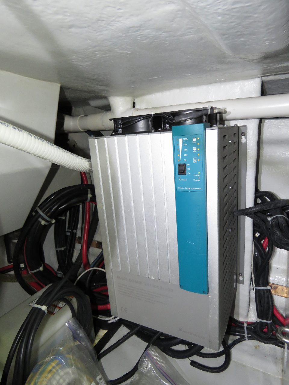
Our Mastervolt MassCombi 24/4000-100 120V inverter works well and we generally like it but it has always seemed to go into thermal shutdown earlier than it should. The inverter is particularly vulnerable to thermal cut out when it’s more than 80F outside and the sun is shinning directly on the stern. The early thermal cutout on the Mastervolt system is more noticeable underway when we have higher 120V load.
Technically the Mastervolt specification is that the system can produce 3.6kw at 104F (30A@120V) and the Laz is rarely over 100F but, like many specs used to sell product, the spec appears to be optimistic or difficult to achieve in real world applications. This early cut out can be annoying both because it’s unpredictable when it will happen and because the system goes down for more than a minute when it does shutdown.
Mastervolt generally makes an excellent product but we find they can be a bit parental when “protecting the equipment.” As an example of an engineering approach we prefer, consider our two Victron Pheonix 3000/120V inverters that are wired in split phase to produce 6kw at 240V. This pair is rated at 6KW at 240V and yet it’ll produced well over 7KW for surprisingly long periods of time. It’ll start incredibly difficult loads like the SCUBA compressor where the inrush current can briefly exceed 40A at 240V. In fact, it will run any load on the boat. The Victron strategy appears to be to run until it simply can’t whereas the Mastervolt approach is to shutdown when the engineering team thinks it might put equipment longevity at risk.
I think the Mastervolt and Victron inverters are both well-made and well-designed. I just find the Mastervolt protection mechanisms a bit on the conservative side, and perhaps a bit too quick to drop the load. The Victrons run in the same environmental conditions and exceed their specs, while the Mastervolts don’t quite achieve them.
I thought the Mastervolt inverter early shutdown might be caused by dirty air intakes, dirty electronics, or a faulty fan. To a great extent, I was hoping to find a problem that could be fixed since I really would like to get a reliable 30A in a 100F operating environment (well inside the Mastervolt specification).
On Dirona, the inverter is both difficult to get to and a real chore to take down but I felt like I needed to do something. Unfortunately, I found all four internal cooling fans were operating correctly and the system was clean and flowing air freely. All was found to be as it should be so there really was nothing to “fix”.
I gave some thought to the design challenges facing an inverter designer in a marine environment. The design needs to reject water splashes while at the same time providing adequate cooling. Likely because of these design goal conflicts, the air flow on the Mastervolt inverter is pulled through small downward facing vents in the side and pushed out the bottom. Unfortunately the designers decided to fight nature and flow the hot air down. But the bulk of the problem is caused by the circuitous air path and fairly small openings to protect against water intrusion.
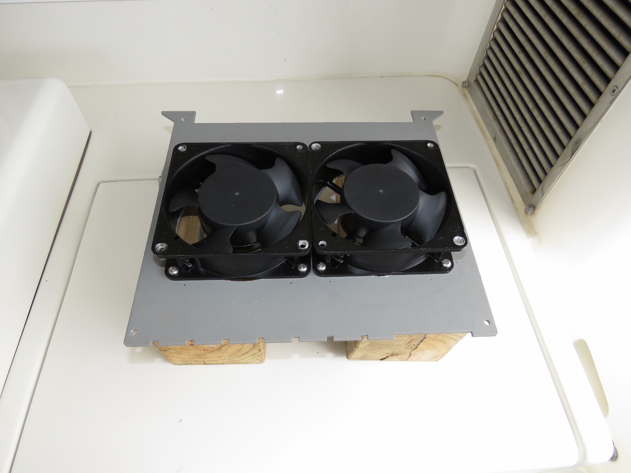
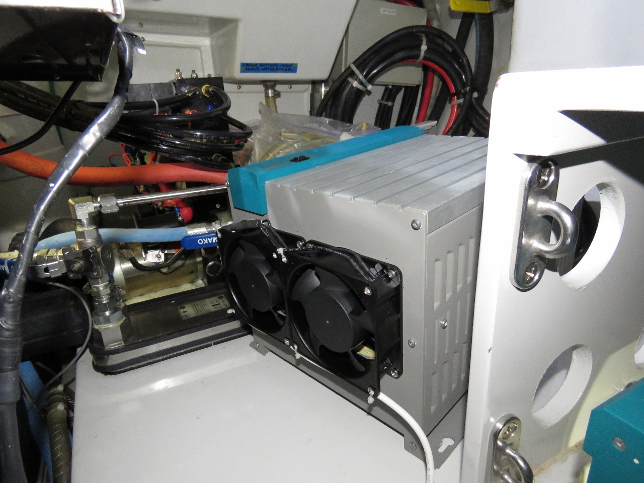
Since we operate in a dry environment where water intrusion at the inverter location is not even remotely likely, I decided to essentially hot rod the unit by opening up two 4″ holes in the inverter top to provide a much less flow-resistant air path. This alone makes a big difference and is now the normal operating mode. In addition, when the laz temperature is approaching 100F, we have 2 55CFM fans that blow down into the inverter case from the top. This dramatically increases the air flow when needed and it really seems to work. We tested the system for more than 5 minutes at a steady 30A to 31A and the system held the load without issue. Much nicer.
We feel like the inverter output problem is largely solved. The final step might be to automate the cooling fan control but it’s working pretty well at this point. A related problem where I don’t yet have a solution is the low voltage derating on the Mastvolt Chargmaster 24/100-3. As the voltage drops down to the 195V range, the chargers derate to about 75% of rated capacity. This charger derating is mostly not a problem and we have run these chargers all over the world on an incredible variety of voltages and currents without a failure.
Arguably it’s unlikely that a 240V system will ever drop down to 195V but some locations like South Africa are actually 220V nominal rather than 240V. The combination of South Africa using 220V as nominal and the high load on the grid means they frequently drop down below 200V, where Mastervolt begins to derate the charger making less output available. A related problem is many countries that use 120V end up supply 208V at the dock. This is common in nany parts of Canada, the US, and it is what we currently have in Barbados. 208V will often drop down below 195V as the electrical grid loads go up.
Overall, I like reliable equipment as much as the next person and there is no question that Mastervolt achieves respectable reliability. But I would really prefer that reliability be achieved with a wider environmental operating range prior to derating or shutting down.
P.S. An offer that is always open to all manufacturers of equipment installed on Dirona: If you want detailed data on environmental operating conditions and results at five-second resolution, we already store everything in a relational database and would be happy to share it with you. It costs us nothing, might improve your equipment, and it’ll certainly improve our experience with it.
Hi James
I have a big overlander truck and after 8 months on the road in Africa I am attempting to better understand and iron out the kinks in the mastervolt systems that I have onboard. I totally agree with your assessment that the Masscombi is a little over conservative for temperature protection and I am quite interested in your forced ventilator workaround. My mane inverter is a 24/4000 with a backup 24/2500 unit which I use to share some of the heavier loads. Have you updated anything with your cooling “hotrod” ? is it temperature controlled or continuous ? if controlled, where did you find was the best place to but the temp sensor please?
I also have a separate issue which you may or may not have encountered. I have asked for assistance from Mastervolt on this one but as always with sporadic issues things work fine when I log in on team viewer with one of their technicians ;(
When I am running multiple heavy loads and I need to top up the batteries I will usually light up the genny (6Kw whisper from mastervolt). My (MV) grid still goes into overload quite frequently when it is only pulling a fraction of I should be able to get out of the generator ??
I have double-checked settings and my prime suspect right now is the “shore” transfer relay is malfunctionning and not allowing the masscombi to use the full amount of current available from the generator before triggering some safety algorithm in the Masscombi.
Any chance you have seen something like this before?
Many thanks in advance.
Kind regards
We wanted to make the auxiliary cooling fans temperature dependent to avoid wasting power when thermal loads where low. The best way to do this is with a thermal sensing switch but thermal overload and shutdown will happen far more rapidly than any external sensor can detect. You would need a fast acting thermal sensor installed inside the enclosure at the component level. But, since the component heat is directly related to system current output, a simpler system is to trigger the fan based upon AC current output. We turn the fans as the output current gets high and back off again as the load goes down. We played it conservative and turn on/off at 15A output. This yielded efficient no-fan operation at low to medium loads and reliable forced air cooling when output exceeds 15A.
This cooling approach proved to both effective and efficient and we made no changes in subsequent years. The system reliably produced full rated output in even very hot weather.
Looking at your reported problem of not being able to draw the full 6kw from your generator, the Mascombi is a fairly complex system with a wide variety of options with uneven implementations. From this spec (https://www.mastervolt.com/products/mass-combi-24v/mass-combi-24-4000-120-120-v/) you can see that Output 1″ is just a shore power wrap around and doesn’t include the inverter. It’s rated at 50A but it’s only powered by “shore power” (your generator) and not the inverter. Output 2 is rated at 25A and won’t supply above that. From the manual (https://productimageserver.com/literature/ownersManual/57552OM.pdf) you can see that the inverter supports Generator Mains Support or power support but not both. In my experience the Mastervolt Mascombi is a solid inverter but many of the more advanced features can be complex to get working and are full of complex restrictions and constrains. I would go for the simplest configuration you can use to achieve your goals.
If I’m reading the manual correctly, the inverter Output 2 AC output is limited to 25A (3kw) and Output 1 is 50A (6kw) but not inverted. There is a diagram in the manual is referenced above on page 11. Recommend not using the more advanced features if you can avoid them and then carefully measuring current into and out of the inverter to find the issue.
The Masscombi supports a variety of dip switch settable
You mention here your 240v inverter setup is two 120v inverters running split phase. Elsewhere you mentioned your generator isn’t split phase, but rather is a single 240v phase. What drove your decision to go split phase on your 240v inverter vs a single phase?
Hey Alec. I was incorrect when I said the generator is a not split phase. What happened there is that I know that the shore power is 3 wire (not split phase) but the boat requires 4 wire (split phase 240V) for some appliances. There aren’t many but the fridge and dryer definitely do have some 120V control logic and need the neutral connection. HVAC, SCUBA compressor, etc. do not. The reason 3 wire (not split phase) works on the shore power is the boat is equipped with an isolation transformer that takes 3 wire 240 and produces 4 wire, split phase 240V. Knowing the shore power was not split phase I incorrectly assumed that the gen wasn’t either but, on a quick read if the wiring diagram after reading your question, the generator is split phase. Nice catch.
The generator is a 240V, 60hz, single phase system that is wired to produce a 4 wire output (split phase 240V) for delivery to the boat 240V system. The 120V system is an unusual design that doesn’t use the North American conventional split phase approach where the 120V service is spread over two phases. Instead it takes 240V through a step down transformer to deliver a single phase of 240V power. As a consequence, there is almost no use of split phase 240V on the boat but the fridge and washer/dryer do need it.
Ah excellent. Lest you think I’m crawling your blog looking for inconsistencies that is not the case, I have an actual purpose :-)
I’m installing a 240v inverter and high output alternator, on similar reasoning as yours about running a generator for modest or short lived 240v loads being less than ideal, and am designing the system now. I was hoping I could get away with a simpler design and just do a single 240v phase (because like Dirona I also have a separate 240v system from the 120v system). Alas, like you I have a 240v washer/dryer that requires the four wire setup. To meet this need, I’ve decided to go with a single 240v 5kw inverter with an autotransformer vs two 120v inverters. It seems simpler and if I do ever end up needing to use any 120v loads off of it I won’t have to worry about phase imbalance across the inverters. Plus I don’t need more than 5kw. If I needed 6kw like you then the split phase inverter would likely be the simplest route.
That is the other alternative but the downside is you lose 5% efficiency in the autotransformer. My take was that was more than I wanted to give up so we went with the dual 120V inverters. One approach is slightly less efficient and the other is slightly more complex but either will work fine.
That’s interesting; where are you seeing 5% efficiency loss for an auto-transformer? I think that when you have phase imbalance that is where you can lose efficiency. Were you referring to when you need 120V power off of your 240V inverter it’s more efficient to use a 240V->120V vs a single 120V leg off of the auto-transformer? I’m pretty sure if the legs are more or less balanced coming off the auto-transformer there is very little loss in there.
Either way, the 5KW 240V inverter, an auto-transformer, and a 220A 24V alternator is working out well. I haven’t wired up a backup for the 120V inverter yet but I’m keen to do that as well.
Thanks for the inspiration! My original instinct had been that it was foolish to run 240V loads off of anything but the generator, but the numbers are clear. Making water underway without the generator running is a great feeling.
240V to 240V transformers have a loss. Autotransformers are more efficient but they still have losses. At high load, you will feel it quite warm. If you get everything right, you can get this loss down in the 1 to 2% range. Nothing wrong with the approach you have taken and autotransformers are super reliable if operating in good environmental conditions.
Totally fair point; by definition the transformation work has to be powered by something, and it’s yet another device in the middle. Using the heat as a proxy for the efficiency isn’t something I’d considered, will get out the heat camera next time it’s cranking and see what it looks like. It makes perfect sense though; and also drives home the power loss to heat on alternators!
Your right on large, low voltage DC alternators being super inefficient. Ours run above 250F at full load.
James:
Just a thought:
What about fastening a ribbed heat sink on the outside of the inverter cabiinet (similar to heat sinks on CPU’s)
Given that I don’t know the temperature of the cabinet (or its design) but if the delta T between ambient and the cabinet is large enough this may be worthwhile.
If there is sufficient room inside the cabinets to mount heat sinks on the offending heat sources??????
Hope you and Jennifer are better able to enjoy the sights of B’dos. Unless you have a very large restaurant buget beware of The Cliff – very good but $$$$$
All the best
Rod
That’s a good suggestion Rod. There isn’t room in the cabinet to easily install more heat sinking but the heat rejection design is based upon a combination of active cooling with fans inside and conducting heat to the the case through direct physical attachment to internal heat sinks. Large heat sinks on the case would likely help but, at this point, more air flow appears to be solving the problem.
Back in my PC building days I would get cabinet cooling products from http://www.frozencpu.com/ and they worked well and have temp controllers. If those are standard 120mm fans you installed then they probably only use 10w each and are DC? I did not see how you wired it in but Amazon has inexpensive 12v temp controllers and even 12v remotes that would work nice and allow you to turn them off. I would even go lo-tech and epoxy a small mirror above the fans so I could see them working without having to go back in there. It looks tight.
I’m using 120V 4″ fans on this one. Right now it’s on a pilot house controlled switch but since my control softare knows the laz temperature and the inverter load, I might eventually automate it.
Even when the fan isn’t running, the inverter can handle more load. I’ll probably leave it manual for at least a few months. Perhaps after I get digital ouputs driven by my Raspberry Pi. Right now I’m only using it for digital input.
You are right about the space being very tight. Good idea on the mirror. The low tech solution is to (carefully) touch the hub of the fan to check for rotation :-).
James,
Is your control system software/hardware documented on this site? I would be interested in seeing how you built it. I know you were playing with an rPi which is pretty cool.
Have you open sourced your software by chance?
Thanks for the inspiration you are living my dream. My wife and I hope to be doing the same thing in 10 years.
Yeah, what he said! (Matthew, about the source code to your control software.)
You can find the low level NMEA2000 access here:https://github.com/canboat/canboat.
I’ll also write up a bit more on our approach and how it’s written in a future blog.
The control systems are not documented but enough people have asked that I will do that. They staerted more than 20 years ago on our previous boat when I got tired of NMEA0183 multiplexers failing and wrote my own in software. Then, since I’m seeing 100% of the NMEA0183 traffic, we might as well store it all in a relational database. Then since we had the data in a relational database, I worte a weather display that showed current and past weather conditions and another app that summarized conditions on recent trips.
When we moved to the new boat, we went with NMEA2000. With help from a fellow Nordhavn owner, we found Kees Verujit’s CANBOAT. This is a very nicely engineered system that we use as low level access to the NMEA2000 bus. It’s a nice tight solution and isn’t hard to maintain and Kees has generously open sourced it in CANboat: https://github.com/canboat/canboat
With CANboat as the NMEA2000 interface, I rewrote the code that stores all the data into a relational database so we are back to having all telemetry on Dirona stored every 5 seconds going back many years. Jennifer ported my TripReporter software that reports summary data on single trips or groups of trips. I replaced my weather display system with Maretron N2kview. Maretron has done a super good job of N2kview and it supports both Windows and mobile (IOS or Android) and it is priced reasonably. It would take me forever to reproduce what Maretron has in n2kview and we are fairly dependent upon it. We show N2kview in the salon, the MSR, and the Pilot House and it’s installed on all of our phones and tablets.
Jennifer wrote the software that displays the maps and takes some data from the nav database for display on the web site.
I have recently started to use a Raspberry Pi for digital inputs and have 11 channels in use. I haven’t yet come up with a power efficient digital output solution but plan to implement digital output control as well likely using transisters for low power switching.
I will document the system in one or more blogs in the future but the above gives a quick summary of what is there.
You have probably solved your heat problem but there is one more low tech solution that helped me with the 3KW inverter on my airstream. Instead of mounting it directly to the floor (side wall in your case) I mounted it on 3/4″ by 1 1/2″ hardwood furring strips the length of the inverter. This creates a 3/4″ gap between the unit and the mounting surface allowing more air to circulate around it. It also saved my bacon in a freak plumbing leak since it was elevated off the floor.
That’s a good suggestion that I do follow with the chargers. They have 2″ under them and 4″ all the rest of the way around. On the inverter, I have a 1/2″ spacer on one side to help it fit better which gives it some air gap and the manufacturer designed in a bit of an air gap as well by spacing the back up from the connecting edges. So, I probably have a bit more than a 1/2″ on one side and a bit less on the other. There is no question that air flow really helps with these issues.
Hi J&J
I have commented before but no show or response, so not sure if I’m doing something wrong, or……
Anyway, I have a half dozen photos of Dirona taken a few days ago whilst we were in Barbados. We had hoped to come and say Hi, but instead we passed you in a Pontoon boat from St Peters resort where Elaine’s cousin manages sales.
If you would like them, please let me know where to send them.
Best wishes, Tim Morris
Hi Tim. If I missed something on the web site from you, my appologies. I’ve not seen anything. Jennifer did get email from you and we did get back to you on that one. Perhaps it fell into your spam folder?
Whatever the cause, feel free to drop by if you are still in the area. Yes, we would love the pictures. Please send them to jrh@mvdirona.com or post them somewhere and I’ll download them. Whatever works best on your end. Thanks for chasing us down.
Thanks for sharing that nice out of the box thinking about improving the inverter James. Hope Jennifer is making a speedy recovery. Glad to see she is still in good spirits!