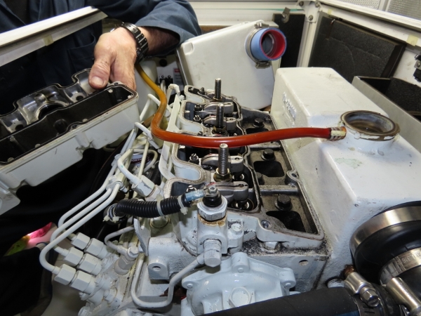
Our Northern Lights 12kW generator ran for years without any hard-to-diagnose problems. It just ran, and that’s the way we like it. For its entire 6,600-hour life, it’s been able to reliably produce 42 amps. It’s nominally a 50-amp generator, but due to highly non-linear load on Dirona, the power factor often is less than 0.85, so full output is 42 amps. Five days ago, however, it started to show an 8-10% degradation in power output. The maximum output had dropped down 4 amps to 38 amps. The generator was down on power, and was declining quickly. Since it’s only an 8-10% reduction, the concern was not urgent. But we rely heavily on the generator and really want to see it running properly.
In troubleshooting the issue, we stepped through a variety of checks and mitigations before eventually solving the problem. And then we found a second problem, either hidden by the first or possibly it occurred during our testing. It’s great to see the generator back to full power output and now comfortable running at 42A, exactly the same as when it was new.
 |
Air Filter
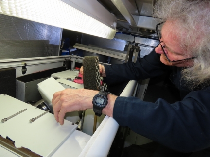
We started with checking the air filter for blockage. It’s in good condition and not the source of any problems. We cleaned up the air filter and re-installed it.
|
 |
Secondary Fuel Filter
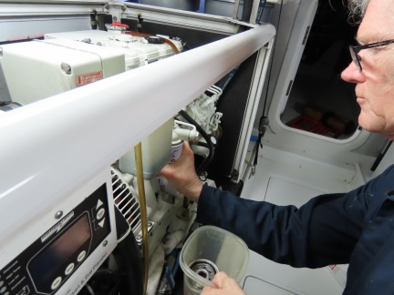
We next changed the primary and secondary fuel filters since they are both close to due to be changed and then need to be eliminated as a cause of the generator output power degradation. Here we’re replacing the secondary fuel filter.
|
 |
Draining Filter
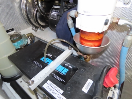
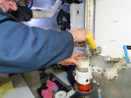
Here we’re about to drain the fuel out of the housing for the primary fuel filter, a RACOR 500. Normally there’s clearance to drain fuel out of the bottom of the fuel filter housing, but in this case, its directly above the wing/gen start batteries. So we screw in a temporary drain hose allowing us to drain it without making a mess. When we’re done, we close the value, remove the temporary drain hose, and change the filter. In doing this job, you only need to drain the housing down a half-inch or so, just enough so it won’t leak when the cap is removed.
|
 |
Primary Filter
Replacing the primary fuel filter. It looked fine, but was nearly due for a change anyway. In subsequent testing, the generator still is down on power. The next thing we’ll likely check is the valve adjustment, since it can cause a reduction in power and the job is due to be done in 369 hours anyway. Another possible cause would be an exhaust restriction, but that doesn’t seem very likely. Exhaust restrictions typically only show up on engines run with chronic low load or heavily corroded cast-iron exhaust elbows. Our average generator loads are quite high, and we’re using a stainless steel elbow. We’re also not exactly sure how to easily check exhaust back-pressure. |
 |
Load Shedding
It’s completely the wrong time to be making changes to the load-shedding system since the generator currently is operating 8-10% down on power. But we started the work on load-shedding before the generator started showing these symptoms. The load-shedding system allows the boat to operate more like an apartment without power limits. Normally, if a hair dryer is turned on when the microwave is on, the generator can be exposed to overload and will either let the voltage sag or it will stall. With load-shedding, the least critical devices are shed to make it appear to a user that the boat has unbounded power.
On Dirona, first the water heater is shut off, then charger #2, then charger #1, etc. This allows us to run the generator right near its peak output, which is both more efficient and better for the generator. But when running near the capacity of the generator, any new load coming in will be too much for the generator. With load-shedding, some non-critical loads are briefly taken off-line and then turned back on when the peak load passes.
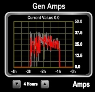
Speed is the key with these load-shedding systems. Our system was put in place five years ago and James recently has made changes to allow sub-second response. The graph shows it’s working well with known amperage draw spikes. It’s smoothly and quickly capped near the max capacity of the generator. You can also see that the max capacity of the generator is significantly below where it should be. We’ll need to get that problem understood and solved soon.
|
 |
Gen Run Profile
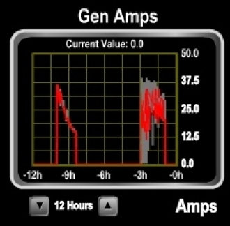
This graph shows the impact of load-shedding on generator operation. In this test of the new load-shedding system, we have the water maker, all chargers, water heater, dryer, and HVAC systems all running hard. This load is far above what our generator can deliver, so the challenge for the load-shed system is to keep the loads operating as much as possible, but not to allow spikes above the generator capacity. The graph shows two things clearly: 1) the new shed design is working very well and it’s keeping all these loads on as much as possible but avoiding generator overload, and 2) the gen load-carrying capacity is way down. The good news is the shed code is working very well but the bad news is the generator has some serious problem. It’s way down on power.
|
 |
Stanadyne
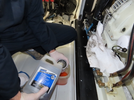
Here we’re filling the fuel filter with Stanadyne fuel additive that we’ll run through the system. We don’t regularly use any fuel additives on Dirona, but have some Stanadyne on board to run through the fuel system when there is a fuel-related problem. Many report problems solved by this treatment, so it’s a resource we keep on board.
In the picture, we have taken off the fuel filter, dumped the diesel inside, and are filling the filter up with Stanadyne. We then put the fuel filter back on, bled the fuel system, and briefly ran the engine to move the additive into the fuel pump and injectors. We left it like that for an hour and then started the system and put it into load. In this case, this didn’t solve the problem, but it’s an easy thing to try. It’s looking more and more like this is going to be a tough one to track down.
|
 |
Removing Elbow
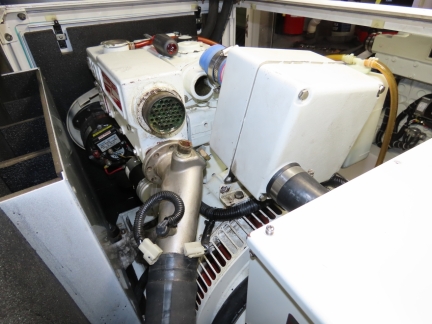
We’re now checking the stainless-steel exhaust elbow for blockage as the next step in debugging the issue. To remove the elbow, we took off the air filter at right, which is held in by two bolts and a hose clamp, removed the two hose clamps that hold the exhaust hose to the exhaust elbow, drained the engine coolant, removed the heat exchanger end cap and, finally, removed the four fasteners that hold the elbow in place. This picture shows the elbow detached from the engine (green circle above it) with the detached the air filter at right.
|
 |
Elbow Clean
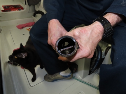
The exhaust elbow looks perfect, with no evidence of blockage. This is a common trouble spot on generators that run at chronic low load levels. They coke up in this area, restricting the exhaust flow and reducing power. Another fault mode is that when cast-iron exhaust elbows are used, they can corrode at this point and restrict flow. This stainless steel elbow has been installed for three years and looks about as good as you get. There’s no buildup at all inside this elbow—it looks almost new. This shows us that this generator is run at very high average loads. The load-shedding system we discussed earlier is good at keeping the generator running at nearly maximum load but not going over. This is one of the positive results of those systems.
We know we don’t have an exhaust elbow obstruction, but we’re still 8-10% down on power. Another trouble spot is marine growth at the exhaust outlet thru-hull. Our system was installed with wet exhaust air/water separator to quiet the exhaust. In this design, there is an underwater through hull where the generator cooling water leaves the boat and an above water through hull where the exhaust exits. If the lower one underwater plugged, water would flow out the upper one and the exhaust would not be blocked. Since water is not flowing out the upper opening, its clear that this part of the exhaust system is also flowing properly.
As we inspected the exhaust elbow, Spitfire arrived to do some additional troubleshooting.
|
 |
Broken Bulb
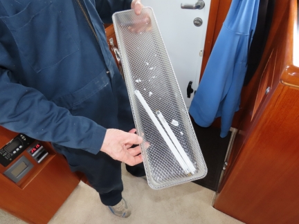
Space is tight between the top of the generator and the engine room light above it. While James was working across the generator, jammed in between the light and the generator housing and working to free the exhaust elbow from the exhaust hose, he bumped the light above him and broke the bulb. We carry lots of spare bulbs, so this was easily fixed.
|
 |
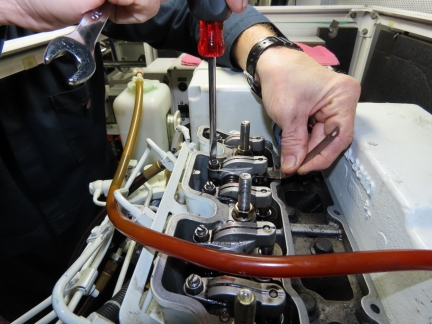
Valve Cover
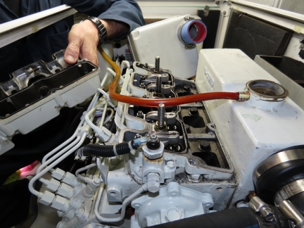
We’re still 8-10% down on power with the generator and continuing to chase the issue. It seems kind of amazing we haven’t found it yet. The air filter is clear, the exhaust through-hull is clear, the exhaust elbow is clear, the primary fuel filter is new, the secondary fuel filter is new, and the valves were adjusted 640 hours ago. The valves only need adjusting every 1,000 hours, but poor adjustment could cause loss of power. This isn’t very likely the problem, but we’ve checked just about everything else. We were debating whether to change the injectors or check the valve adjustment next, we were leaning towards changing the injectors since there are 6,658 hours on them, and valves aren’t due for adjustment for another 360 hours.
James talked to Northern Lights expert Bob Senter (aka Lugger Bob) and he said the injectors can get pretty bad in these engines without having much impact. Bob is exceptional. He recommended to check the valve adjustment since the injectors really have to be in bad shape before they start causing problems. We’re not seeing any smoke or other indications of injector problems so off comes the valve cover to check the valves. We’ll need to move along without wasting too much time since we’ll need the generator to start in another hour or so to charge the batteries.
|
 |
Adjusting Valves
James adjusting the valves. He found found both intake and exhaust valves were tight on cylinder #3. Usually valves clearances don’t change much over time and, if they do, it’s more common to get looser over time rather than tighter. In some ways, it’s good to find a potential problem. It’s not clear if this is A problem or THE problem causing the 8% to 10% power reduction, but certainly it is a problem.
|
 |
Generator at Full Power
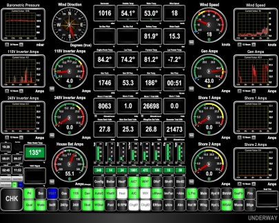
The valve adjustment solved the problem! It’s great to see the generator back to full power output and now comfortable running at 43A, exactly the same as when it was new. You might wonder why a 50A alternator is “running perfectly” at 43A. Most generators are rated at a power factor of 0.8 since most generators operate into a less-than-optimum power factor. Northern Lights follows suite and all of their three-phase generators are rated at a power factor of 0.8. Their single-phase generators, however, are rated at a power factor of 1.0, but our power factor is often as low as 0.84. This isn’t a problem, but it does mean a 50A generator is actually a 40A producer at a power factor of 0.8. On our boat, we can reliably get 42A and typically run with a 42A limit. Here we are testing at 43A to ensure that there is engineering margin of safety and we will be able to run at 42A without issue.
|
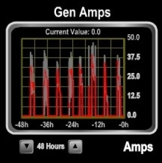 |
Gen Run Profile
A profile of our last 8 generator runs in the past 48 hours. The red lines show average load and the grey are peak. The first four on the left are before the valve adjustment,, where the average loads were barely 30 amps with brief peaks of up to 39 amps as the generator went into overload. The fifth run is testing right after adjusting the valves, where we are probing the limit of output the generator can produce. It’s nice to see it back to being able to hold a steady state 43A with brief excursions above. The next two runs are back under generator autoshed control where we shed at 42A (some engineering safety margin off peak) and only provision charger loads to 41A, again to allow some safety margin. Those last two graphs are the generator 100% back to normal in our usual operating pattern of letting autostart start the generator when the batteries get down to 55% and then shut if off again at 85%. While charging, load-shedding keeps the generator load below 42A.
It’s nice to see the generator able to produce exactly the same power it could produce when it was new 10 years and 6,658 hours back. It took a bit of work to find the problem that was reducing generator output by 8% to 10%. We’re glad to have it behind us, but the question remains, how did the valves get so far out of adjustment in only 640 hours? The manufacturers valve adjustment recommendation is 1,000 hours so this is quite early and, normally, valve adjustments don’t change much in well-maintained engines. We can only come up with two possible explanations and we don’t like either of them: 1) “previous mechanic” error, and 2) valve or valve seat problems. On the former, we know the “previous mechanic” remarkably well and he’s usually conscientious and reliable. We would hate to reach that conclusion but we would hate the thought of a deeper mechanical problem even more. The generator is running as new so mechanic error is the likely prognosis. If the system continues to operate well for 10 to 20 hours, that’ll be a clear signal that there are no continuing mechanical issues.
|
 |
Running Hot
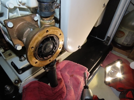
We were hugely relieved that the valve adjustment resolved the 8-10% power output degradation with the generator. But it was producing full output at 198F when it should be done in the 186-188F range. Something still wasn’t right.
When a wet exhaust engine has a heating issue, the first check is to look at the raw water pump impeller. Here we have dropped off the cover on the raw water pump to check the impeller. Predictably, some of the impeller fins are missing.
|
 |
Heat Exchanger
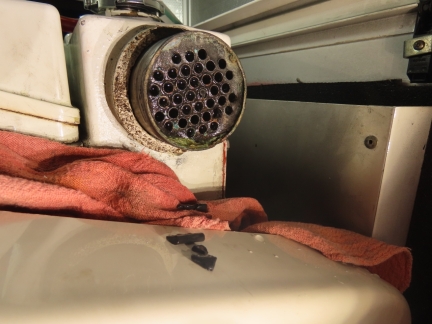
The most important part of a raw water pump impeller change is to ensure that any broken fins are recovered. If you are lucky, the fins are cracked but only large fragments have broken free. And, if fin parts are missing, they always end up stuck against the inlet of the heat exchanger which will cause the overheating problem. Here we have drained the engine coolant and taken off the heat exchanger end cap. You can see that fin fragments are have fallen out upon removing the cap and, if you look carefully, you can see one of the heat exchanger tubes near the center actually has a rubber fragment in the tube. This is rare, but we were able to pick it out with a large needle
|
 |
Broken Fins
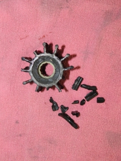
We put the old impeller and all fragments together on a rag to ensure that we’ve found them all. If any fragments are missing, you need to keep looking. Raw water pump impellers are a wear item and replacing them annually is pretty common. Most people change them annually but we’ve noticed that the shortest an impeller has lasted us is 1 day and the longest is 3+ years (and it didn’t actually ever fail, we just ended the experiment early and changed it).
Because impeller lifetime varies over such a large range, we don’t proactively change them. We just change them when needed. But, if you wait until the engine overheats, it’s very likely that fin bits will come free and this makes the replacement job more lengthy. What we have noticed is that if the generator goes up over 192 to 194F, the impeller needs changing. So we set a yellow warning light and send email at this temperature. This often allows the impeller change to precede the fins breaking free. We also trigger a red warning light and an email message at 200F, and the system automatically shuts down at 205F.
|
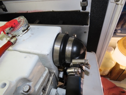 |
Heat Exchanger End Cap
The Northern Lights heat exchanger design is an unusual one that doesn’t require an anti-corrosion anode. What they do is float the heat exchanger between rubber heat-exchanger end caps on each end. Since the bundle doesn’t ground to the engine, it doesn’t require a zinc anode. These end caps are heavily made and last very well through many reuses. Today we changed one after 10 years and 6,663 hours of use. It’s getting stiff and starting to distort a bit, making it harder to get the clamp to engage properly with the heat exchanger bundle. The old one still works fine but a new one is easier to work with, so we changed it.
|


Hello James,
I sure like all your technical explanations on how systems work and how you walk though problems until they are solved. This is the first time I have heard of Power-shedding. The way I understand the power system of a boat is, everything is run off the batteries and inverter, when your batteries are down to 55% the generator will start and charge the batteries. How does the power-shedding work when the generator is running?
There are two issues here. The first is power management. Some boats run the generator 24×7 and they only way they can run power appliances is to run the generator. Another approach that is getting increasingly popular is to run the boat off of a large house battery bank and then to start the generator if the batteries become discharged. This the approach we take on Dirona. Manual generator operation is a perfectly good option but to make the starting and stopping of the generator be less error prone and to allow us to be away from the boat for longer than expected periods without damaging the batteries by deep discharge, we also implement generator auto-start. On Dirona the generator auto-start system starts the generator when the batteries get down to 55% and then shuts it down when the get up to 85%.
The second issue is load shedding and it’s an approach to automated power management that applies to the generator, inverter, shore power or any other power source. Here’s how it works. Whenevern there are electrical loads running on a boat, they are powered by some power source. It might be the generator, it could be the shore power connection, or it could be the inverter. But, whatever the power source, it’s bounded. different power sources have different bounds but they all have limits. Our generator is 42A. A common shore power configuration in the US is 50A. In Europe 32A and 16A is common. Our inverter is 25A. Because some of these bounds are quite load and all are lower than you would expect to find in most appartments, they power has to be managed. You need to make sure that nobody puts a hairdryer on when the kettle is on. The microwave isn’t used at the same time as the kettle. The dryer and HVAC or Oven aren’t used together. You need to manage the loads to below that of the current source which means that somebody has to know the current source and everyone has to communicate. It’s often the case that when a hair dryer is going to be turned on, the user will yell that they are going to do that.
We don’t like that model so we implement load shedding. Load shedding is an automated system that knows the power source limits and prioritizes all the electrical loads so that the most important loads get the power. This avoids over drawing the power source and takes away the burden of power management. When the 240V system is overloaded, our system first temporarily disconnects the water heater, then the second charger, then the first charger, then the HVAC system. This gives the feel of an unbounded power source and takes away the hassle of load management. The system just turns loads off and on to keep the draw within the capabilities of the power source. It makes the boat feel like it has no electrical bound just as most houses and apartments feel that way. They all have bounds but in the cases of houses and apartments in many parts of the world the limit is so high that it’s rarely if ever encountered. Shedding gives the same feel when power sources are more constrained.
Thanks for this great explanation. So they way I understand this is all the managed loads would be wired to a devise and a program would
turn off and on the load. What would the brand of your power shedding devise be or is this something you have designed yourself?
Load shedding systems are not that common on boats but they are showing up in higher volume in the RV market. Generally what is required to implement a load shedding system is to have a sensor to measure how much power is being draw, a controller to control loads, and then a set of contractors, relays, or remotely controlled breakers that can be used to turn loads off and on. Ours is a custom design but there are many commercial systems out there. Usually these systems are referred to as Energy Management Systems (EMS) and you can find a lot of alternatives searching for “EMS and load shedding” but that query will find some very large commercial systems used for managing multi-megawatt loads on oil rigs. The search for “RV EMS and Load shedding” narrows things down to systems that work well our scale.
This article is a good place to start: https://www.rvtechmag.com/electrical/chapter12.php. As an example, they using an Intelellitec system which is fairly broadly used in the RV world: https://www.intellitec.com/products/.
We have a motor home with a 12kv generator and we are running into the problem
of running too many things at the same time. So when I read your post on this topic I was all over it. You have been very helpful. Thanks.
Glad to hear and your application sounds almost identical right down to the same size generator. If you do implement and Energy Management System with load shedding, you’ll love it.
Hi James,
Enjoyed your latest post regarding lost power on the gen.
I am probably misunderstanding this stuff, but I do not get why your gen can produce only 42 amps. The amps are just a measure of apparent power. So it seems you should be able to get to close to 50 amps on your 12 KVA generator (not that you would want to run at 100% all the time). Real power, on the other hand will be less since your power factor is 0.8– in that case your real power is around 9.6 kW. Or, is your monitoring system actually measuring real power rather than apparent? In which case I understand why the max amps are lower than 50.
Hi Ron. Thanks again for sending me your data on rear main oil seal changes. It’s excellent and we really appreciate you putting it together for us.
The gauge is reporting amps produced but, my understanding is that our leading power factor will tax engine output and, as a consequence, it only has the power remaining to produce 42A. In a large electrical utility Amps produced is apparent power but in a small generator the energy consumed by all that reactive energy reduces the engine power remaining and the apparent power it’ll produce will be diminished. Normally what we are used to seeing is some energy going to reactive power and the rest being delivered as real power but with a small gen, then engine only has some maximum HP prior to stall. All the reactive energy is load against the engine and will show up as engine work without result. The actual power produced measured in Amps is what that engine can produce with the remaining HP.
If we ask more of it than 43 to 44A, it’ll stall. It’s been that way since new and it was a concern at first but it’s rock solid and reliable there and that number stays the same (unless there is an engine problem) so we just use 42A as our limit and operate that way. That’s up over 10kw so we’re pretty happy with it and we run up there for extended periods but, if there were a way to get the full 12kW, we would certainly take it.