Isolating shore power from on-board electrical systems is important to avoid excess corrosion and, even more importantly, to avoid risk of shock in and around the boat. Two common approaches to isolation are galvanic isolators and isolation transformers. Isolation transformers have many advantages and often are installed in Nordhavns, but have one potential downside though: when first plugged in, a substantial but very short current inrush can occur that can trip shore pedestal breakers.
It’s no big deal, as the problem may occur only once or twice in ten plug-in attempts with a 16A connection and rarely with higher-amperage shore power connections. Many boaters will never plug in an isolation-equipped boat to 16A or less and, for those that do, a breaker only rarely trips and a simple reset will clear problem without another thought.
The problem is intermittent in that it depends where in the shore-power sine wave the load is applied. If the load is connected near the zero crossing of the utility electrical sine wave, there is no problem. However, if applied further away from the zero crossing, the inrush currents can be very high and shore power breakers can trip. These inrush currents are short—far less than a second—but they can be up over 100A. In the old days of low-quality breakers, the short-duration high-current draw went unnoticed. But modern circuit protection devices will trip on even short-duration inrush currents.
For many boaters, this is a just a bit odd in that when plugging in they occasionally trip a breaker but, upon reset, it’s fine. Many attribute this to the act of plugging in causing an “unusual transient” and they don’t give it another thought. But this can be a big problem in some conditions. For example, if a short power interruption occurs when we are away from the boat on an extended trip, the breaker may pop when the power returns. Again it’ll be fine on reset, but in many of these conditions nobody is there to reset the breaker. What we want is a design where we can cycle the power hundreds of times and never see a breaker release.
The solution is a soft start and several very nice commercial solutions to this common problem are available that will work fine for many applications. For example the Charles 93 XFMRSOFT-A 120/240 VAC Soft Start Module and the Mastervolt Soft Start 13kW. Both are explicitly designed to eliminate this problem and both look to be well-engineered. We looked mostly closely at the Mastervolt solution since we have lots of Mastervolt equipment on the boat.

The Mastervolt soft start switches a 25-ohm resistor into the circuit for just under 20 msec on circuit energization and then removes it from the circuit. The resistor is there to slow the inrush and, as soon as that is done, it’s taken back out of circuit. Arguably Mastervolt is charging quite a bit for this simple device but, in the grand scheme of things, it’s not excessive and a packaged solution is by far the easiest to deploy.
We would have done this were it not for two aspects of the design we didn’t like for our specialized application: 1) we need to limit the inrush to not cause breaker release down at 6A or 8A (very low amperage shore services are the norm in some places in the world and we are wired such that we can run the boat from two independent shore services allowing these to work for us), and 2) the Schneider contactor they are using as part of the design is a 50hz rated part but we need to be able to support both 50hz and 60hz shore services. Solving the first problem requires using a slightly higher resistance resistor and the second problem requires a contactor rated for both 50 and 60hz. Both are easily available.
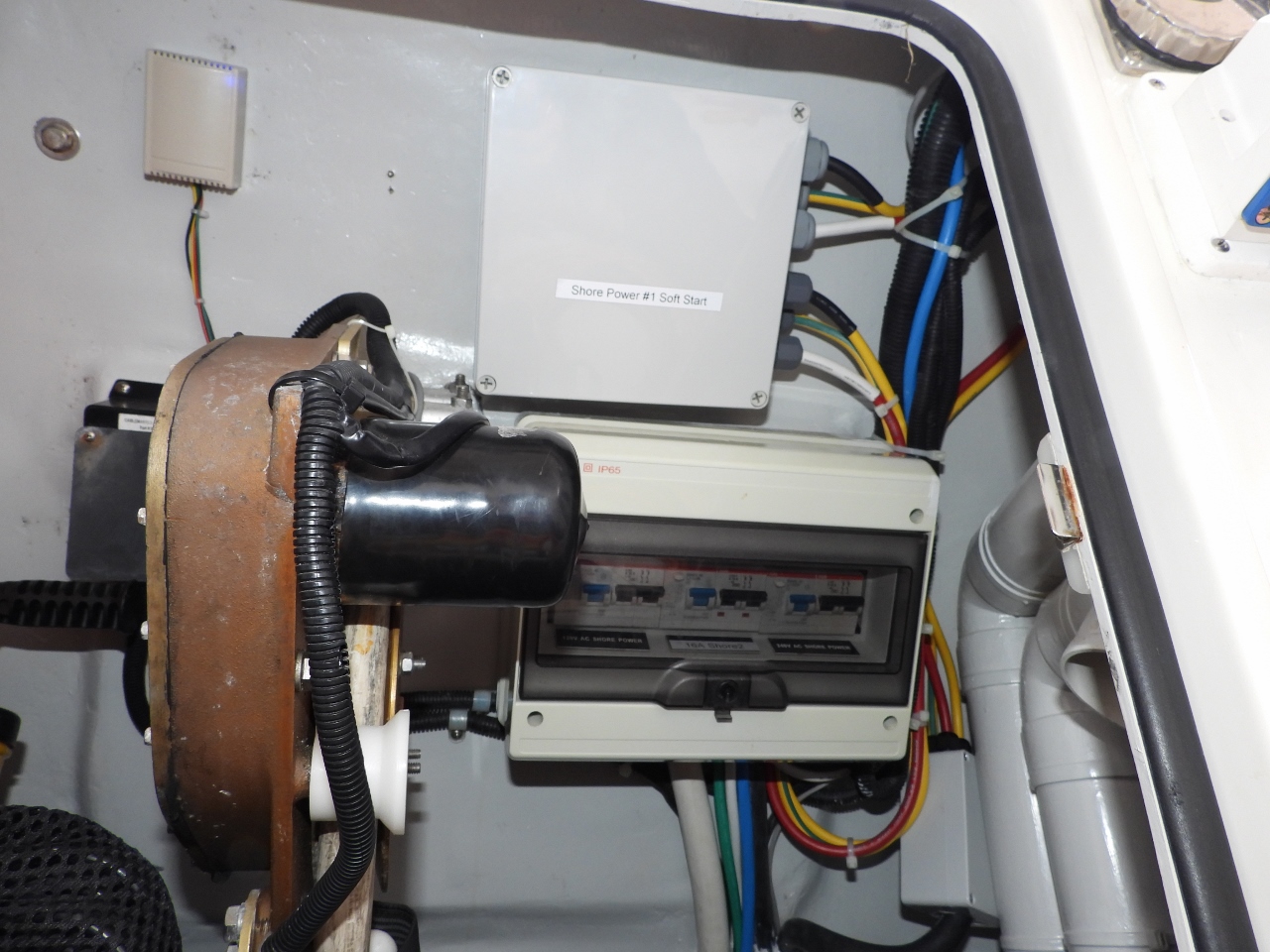
What we’ve built and installed on Dirona, pictured below, is a fairly simple device that puts a 40 ohm resistor in circuit for half second to slow the inrush from a maximum of up over 100A to no more than 6 to 8A. After a half second (500 msec), the resistor is taken back out of circuit.
Right at the location where shore power is brought into a boat, there needs to be an overload and fault protecting breaker before the power is routed to any other electrical device. A well-designed system also include a residual current protection device (RCD) at this point as well. In the pictures below the soft start is installed just above the shore power on-boat breakers. The power flows from the shore power pedestal to the boat through the shore power breaker and the RCD, and then through the soft start before heading to the on-board isolation transformer and the power distribution and breaker panel.
|
|
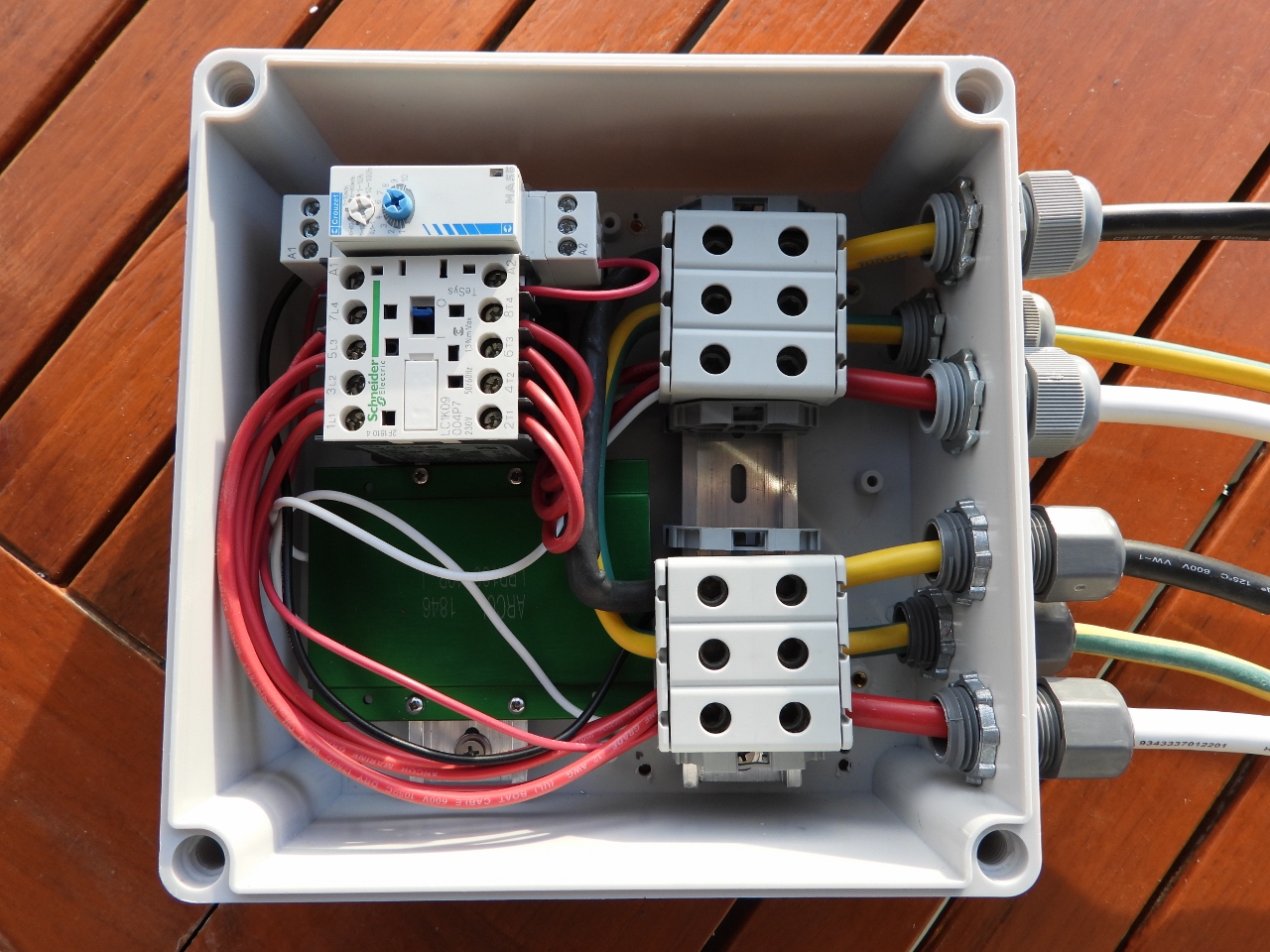
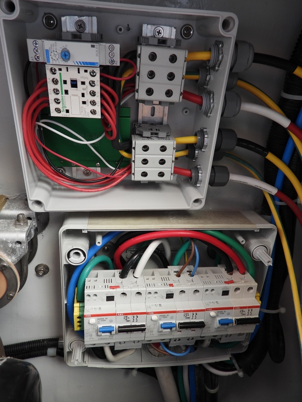
The softstart is installed immediately after the shore power breakers in the lower right hand corner of the pictures (visible in both
—click images for a larger view). From left to right in the lower junction box are the breaker and RCD for each of the three shore power systems supported on Dirona; 1) the 30A @ 120V shore power system, 2) the 16A at 240V second shore power system, and 3) the 50A at 240V primary shore power system. The soft start is connected between the right hand breaker and RCD on the 50A primary shore-power feed between the shore power breaker and the shore power isolation transformer. The top junction box is the soft start system that puts a 40 ohm resistor in series with the shore power for 500 msec (half second) before the soft start system switches the resistor back out of circuit.
If you look closely at the pictures, you’ll see the wires in and out of the soft start are unusually large. These are 6 gauge conductors (nearly 1/6″ of an inch in diameter) with heavy insulation. This seems needlessly large but the circuit is rated to carry up to 50A and can support loads of 12KW so the conductors need to be substantial to avoid excessive voltage loss and heating.
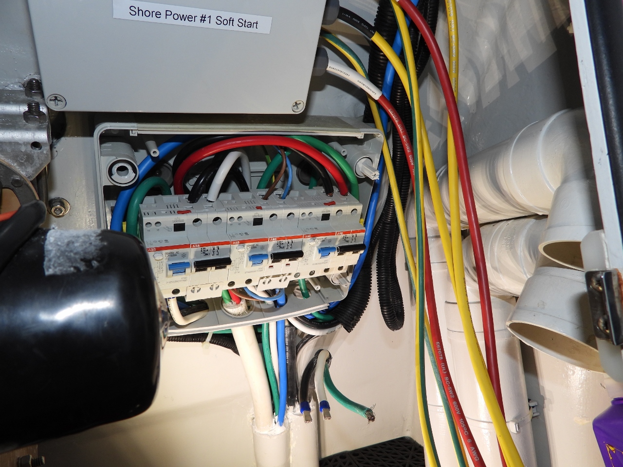
At the point in the project shown in the pictures above, the wires are hanging down below and to the right of the soft start system but they are not yet installed. The next step is to bring down the shore power and run the boat on batteries while the final wiring is completed.
The picture above shows the completed soft start system installed above the shore power breaker box. The City Marina in Amsterdam, where we installed the system, was a particularly good place to test its efficacy since the shore pedestal main breaker releases whenever we apply power. Once powered up, it’ll run fine indefinitely but during power up the breaker just about always pops. Fortunately the power is reliable here, but when some electrical service was done in the marina one day and shore power was shut down and re-enabled, each one caused the pedestal main breaker to trigger. We can now plug in and unplug at will, the power can be turned off and on repeatedly, and everything just works. Wonderful!
James, we’re planning our install of two 120V 30A Bridgeport Magnetics isolation transformers on our (much smaller) Monk 36 trawler, and are making room for two soft starts. We’re hip to the notion of using a timed contactor and resistor to control inrush, but space is more limited on our boat, and with two 120VAC 30A feeds we would need two boxes with access. We’ve therefore been investigating solid state relays as a possible alternative, and think that there could be several methods of ramping up Volts-Amps over several seconds to perform the soft-start function. While investigating we’ve a Carlo Gavazzi SSR that’s purpose-built for switching transformers:
https://www.gavazzionline.com/pdf/RM1Cdatasheet.pdf
It’s designed to connect at the peak of the AC waveform, and switch off at the zero crossover, which we understand would avoid the big inrush that can happen when energizing at a random time on the waveform.
We’d gratefully accept your opinion and experience on whether you considered the Static approach for Dirona, and whether the concept is worth testing.
The approach of connecting current at peak as the voltage is heading down is an interesting approach. Certainly it’s conceivable that it would work. It sems credible enough but my only worry is when searching for transformer inrush solutions, there are many but the solid state relay solution isn’t one of them. The other issue with solid state relays is they often dissipate a lot of power and so they both waste power but also require a location where they can dissipate heat. Given that takes a bit more space, I would lean towards the solution we used with the resistor and timed relay. It works well, is super efficient and only requires a small 4″ square box and doesn’t require cooling. But, the solution you pointed to certainly seems reasonable. Whichever path you choose, best of luck on your project.
Thanks very much for the feedback, James. I also had the idea “if that’s the best way, Mastervolt would be doing it,” but I don’t let normally let those thoughts guide me. We’ll keep investigating, and if we learn something interesting about it being a really good (or really bad) alternative, we’ll post the details. Our overall goal is a most-compact assembly, since 36’ MYSTIQUE doesn’t have very many clear spaces available. We’ll happily jettison the concept if it turns out to be impractical.
Hi James, I came across this article while researching the MasterVolt softstart. I have purchased one and am in the process of installing it but had some questions. I am trying to “soft start” a Bridgeport Magnetics isolation transformer(s), which being torroidal have very large inrush. Being in Canada I am 240V or 208V 60 Hzdepending on the Marina so was questioning the connecting wiring.
I am curious about your comment in requirement #2 above about the MasterVolt having a 50 Hz contactor and therefore not suitable for you. I’m not sure why the frequency would matter. But does this mean that it will not work in my 60 Hz environment? Thanks for any info, and keep up the great work!
Good question. You’ll love the Mastervolt softstart. It’ll solve your problem and you’ll really enjoy not having to live with breakers popping frequently when you plug in. It’s a great solution.
You asked about the 50hz issue. It’s a minor issue related to the used to bypass the resistor in the Mastervolt design. Contactors are just switches that are closed electrically with a coil magnetically pulling the switch closed. Some AC coils are rated for 50Hz vs 60Hz and some will accept both. Technically either will work on either frequency but, for maximum life in continuous duty, it’s best to use a contactor that is rated to work at both 50hz and 60hz. Not a huge issues but a dual frequency part would have been a better choice but I doubt you’ll see an issue. You can check on this by taking off the cover and looking up the rating on the contactor deployed in your unit.
The design I deployed has an additional safety factor over the Mastervolt design. The failure mode I wanted protection from is, if the contactor failed and the current is left on the resistor, it will very rapidly overheat and fail. If it just fails open, your fine. But if it causes a fire (slim chance but possible), it’s not great. So I put a slow blow, low amperage fuse in the resistor circuit such that, if the contactor fails, the fuse will release in a second or 2 and interrupt the circuit prior to the resistor overheating. It’s likely that the resistor in the Mastervolt design will quickly just act as a fuse so they may have done the testing to essentially know that they are adequately protected but I slightly prefer the fuse.
Thank-you for your prompt and detailed response. I’m going to plug it in and see how it goes. I’ve had the unit apart for a few days scratching my head a little, but your article really helped. I spent some time with Schneider tech support, but we couldn’t locate an exact replacement except for the dual frequency ability. They make all kinds of these things though, so I’m sure I could have come up with some kind of substitute, but I’m loathe to muck with the MasterVolt design and accompanying ratings. And as the saying goes, these things come with two levers; LeverA and LeverB, if you don’t know how to operate LeverA you’d better LeverB.
Thanks again, and fair winds. I’ll update on progress – smoke or no smoke. 😊
Sounds like a good plan. I know of a couple of Mastervolt softstart deploys that are doing fine. I think you’ll like it.
Thx. Subject to some possible downstream failure for whatever reason I am going to declare this resolved. I connected it and flipped the shore power breaker on and off a dozen times or so, with varying “off” times, and it worked every time. On almost half the tries you could hear the xfmrs give an angry buzz for a couple seconds as they started up. I think those were the 0 line crossing times that previously would have snapped the breakers. I must say these toroidal xfrmrs are very quiet (so far). I had our new Bosch induction range hooked up to my test config, and cranked up pulling 11+ amps at 240V they were silent. Thx again James.
Isn’t it nice to plug in and not have frequently nuisance breaker releases? I had no idea how annoying it was until we installed the soft start. Good luck with yours.
Hello Randy,
So your saying this mastervolt unit worked fine on 50 amp 60hz north american split phase 240 volts? If so im buying one, could not get a straight answer out of mastervolt. Thanks.
It will work fine but it’s never great to operate an electrical device outside of it’s design intent. The contactor used in the Mastervolt system is actually only rated for 50 hz. It would be easy for them to use a dual frequency rated contactor but to my knowledge they haven’t yet made that change. However, I’ve seen the systems running on 60hz and can confirm they still function in this operating mode. It’s possible that the contactor could fail early as a consequence of running outside of it’s rated frequency and, with this design, a failed contactor would leave the current flowing through the resistor and the resistor is not fuse protected. My choice was not to install the device and do my own design only because I’m not comfortable operating the device outside of the rating of the components used in their design.
In what I built, I put a slow blow fuse in the resistor path so that a failed contactor would cause the fuse to blow rather than overheat the resistor. It’s a weakness of the Mastervolt design to not protect against this fault mode. It’s possible they have tested it and the resistor quickly fails open on contactor failure but I much prefer to have a fuse in that path for added safety margin.
Hi James
I am having a problem with the new Bellingham ELCI pedestals in Marathon. I spoke to Mike Telleria at Nordhavn. He recommends an Ametherm nrush Current Limiter 1 Ohms ±25% 50A 2.677″ (68.00mm).
I have ordered one and will place it in line before the isolation transformer input .
I am hoping this will solve the issue.
Ted
Southern Star N47
The Negative Temperature Coefficient (NTC) thermistor is a simpler to install protection so has real advantage. The reason I elected not to take that path is the NTC takes minutes to cool down and regain the resistance needed to protect the circuit. The most common utility outages are very short. Small numbers of seconds are more common than minutes. The NTC solution is not effective on these short outages since it takes several minutes for them to cool down and regain the resistance needed to protect the circuit. So, this approach can’t protect against short utility power interruptions. The upside of the NTC design is it’s simple, doesn’t have unsafe failure modes, and it is easy to install.
Thanks for all the detailed descriptions of all the upgrades you do on Dirona! Very helpful.
Hey Trond. Good hearing from you. The dual shore power is really excellent. When we were in Hoorn, we had only 10A shore power and, as you know, we run our boat like a well heated apartment but it ran well on dual 10A supplies. It looks like we’ll be using it frequently in Sweden as well.
All the best in 2019!
Great it worked out well. Yes, Sweden’s shore power will be more or less like Norway. Theoretically 16A at most, which becomes less if many boats are connected at the same time.
Hope all is well!
(By the way, Dusseldorf, Germany has the largest indoor boat show this week.)
Yes, from what we have heard so far, you are right. Even downtown Stockholm uses a 10A service.
Hi James, your solution to the shore power tripping phenomenon (caused by the large isolation transformer) is characteristically comprehensive.
I am a great fan of keeping everything as simple as possible and believe that anything more complicated than the ‘off the shelf’ Mastervolt solution is perhaps unnecessary. I do however understand that Dirona requires a shorepower system that can cope with multi voltage and frequency inputs that are available around the world.
I have a some observations if I may;
1. You describe the three shore power breakers (with RCDs) as being in circuit between the pontoon pedestal and the isolation transformer. In this location I am not convinced that these RCDs offer any protection except on those cables that connect to the primary side of the isolation transformer. The isolation transformer by definition makes the RCDs fitted where they are ineffective in protecting the internal sockets throughout Dirona. For the sockets to be protected doesn’t any RCD need to be on the secondary side of the transformer?
2. The 500msec delay on the newly installed soft start contactor means that this contactor operates some 25 or 30 cycles after the initial connection to shore power. I am unclear as to how this is of any more benefit over a contactor that switches in during the first cycle. The shore power MCB has two components that protect against over current, one is the fast acting electromagnetic component and the other is a thermal component. In tackling this soft start problem we need only be concerned surely with the first of these protection criteria – a long delay has no benefit.
3. I am not sure if Dirona has multiple input sockets for shore power, in particular separate inputs for the 16A and 50A inputs. It would not make sense to me if there were. With the limited information that I can gain from the blog I don’t understand why a separate MCB/RCD is required for each of these amperage inside the shore power breaker enclosure. On N4736 Wanderlust I simply have a different cable with the appropriate style connector on the end for the task in hand – if I am plugged into a 16A supply but I’m fused for 50A then that’s not a problem if my cable is rated at 50A.
4. I do agree that a problem of thermal overload of the resistor will exist if the soft start contactor fails to energise. Indeed I have come across this a few times in my days of commissioning electrical control panels. I have this very concern over my own installation and also with the Mastervolt product. In my experience though contactor failure is normally preceded by a period of loud buzzing – Just something to bear in mind.
I am enjoying your blog, cheers,
Ian N4736 Wanderlust, UK
Thanks for the discussion below. I’ll tackle each:
1) The RCDs were part of the original electrical design with RCDs on each branch circuit in the bot and a big RCD at the point where power is brought on the boat. It looks like a nice design from my perspective.
2) Does 500 msec really do a lot better than the around 20msec that will be provided by the contactor delay itself. Probably not but it’s close and whenever an engineering design is close I usually add more margin. In our particular power layout the load isn’t brought on for 10 seconds so we have room to add more delay. Because I’m connecting a system capable of running on shore services as large as 50A, the transformer is quite large (12kVA) and we want to be able to use this circuit on circuits as small as 8 to 10A, we need to control the inrush fairly completely so going out to 50 to 100 msec seems like a good decision. 500 is where I set it but I’m sure it would be just as good at 50 to 100. Most of the large scale commercial designs do contain timers so they are using more than contactor latency in their designs.
3) The three different power connections are for three different purposes. The one on the left is for a 30A at 120V shore power connection that is stepped up to just under 16A at 240V and is used only in 120V jurisdictions. The one on the right is a 50A@240V connection and it’s the primary shore power connection and it’s used with shore power connections as small as 8A and as large as 50A. The middle connection is a seconds shore power connection that provides 16A@240V. It’s can be used by itself but the common use case is to use it combination with the primary shore power connection. For example, here in Amsterdam we have both the middle and right had connections fed with 16A on each for 32A of 240V. Having two shore power connections where the draw can be set arbitrarily low is a nice way to make very low amperage connections work with a power intensive application by doubling up.
4) I’ve given some thought to this. One approach is to put a temp sensor in the box and disconnect the load over some fairly high temp like 180F. Ian Cockett suggested a second timer to disconnect the load if the primary contactor doesn’t close. I’ve not figured out how he’s wiring in the second protection timer but it sounds like a good design. The commercial solutions I’ve looked at don’t have protection against this failure mode but, if a simply solution emerges, I’ll probably implement it. The one I’m currently leaning towards is a slow blow low amperage fuse in line with the resistor. Any suggestions on this or related protection mechanisms?
Hi James, with regard to protecting the resistor from overheating (should it have a prolonged connection to the mains voltage) I think a fusible link solution is a good direction to explore.
On Wanderlust I have used a 25ohm wire wound metal clad power resistor, rated at 50W. In the situation whereby the soft start contactor does not successfully ‘pull-in’, this resistor will be subject to near mains voltage for an indefinite time. One thing is sure – it’s going to heat up really fast!
So what happens when it blows? That’s the question.
I was hoping that instead of catching fire it would simply burn out, and being encapsulated in a metal casing it will hopefully be safe when it does.
I calculate that at 230V the resistor will have up to 9.2A flowing through it. This will generate 2,116W so it’s not going to last long. I hope that it will fail before the casing gets too hot.
Taking a look at a possible scenario on Dirona where you may be hooked up to 110V, your 50ohm resistor will pull 2.2A and therefore generate 242W. That will fail too – but it might take a lot longer thus allowing the enclosure to heat up and melt/catch fire. Perhaps you should consider reducing this resistor to 25A to induce a quicker failure. Whether 50ohm or 25ohm it’s not going to make much difference to the soft start device. All the time here we are talking real power and real resistance, in reality we are trying to solve a problem caused by high inductance and an unknown impeadance. It may be a case of ‘try it and see’.
With retrospect I think that I will obtain a duplicate resistor as used in my design and test what happens when I connect it straight to the mains. It will be interesting to see just how it does fail and whether it does so safely.
One last thought on your method of using two shore power supplies to share your power requirements – BEWARE the possibilitiy of connecting to two different phases of a marina supply. The last thing you want to do is stick 415V onto the boat. You should always test first for this possibility as marinas do use three phase supplies and the bollards are usually not marked externally as to which phase they may be on (and would you trust the labelling if they did?).
Best regards,
Ian
N4736 Wanderlust, UK
Ps. All my calculations are subject to human error!
You are using a 25ohm, 50W resistor and I’m using a 40ohm, 100W resistor. The large scale industrial soft starts do include contactor fault detection. The commercial marine units don’t. You may be right that the resistor would overload in a stable way but until you check that phenomena but it’s probably best to consider it unprotected (as are the commercial systems). It would be better to have some backup on this system. My leaning is towards a slow blow fuse in series with the resistor and I’ll probably head in that way but, since the commercial systems don’t fuse, it seems that unprotected is acceptable in the jurisdictions where Mastervolt sells (includes the US and Europe).
The two shore power supplies on Dirona don’t need to have phase aligned power. It works safely and reliably with 60 degrees offset from 3 phase power is fine. And, 180 degree offset is fine as well. They work fine with two non-alighned sources or even one a 50hz source and the other a 60hz source. Not likely but all fine. Neither side plugged in will energize the other side (not what is often called a widow-maker) and there is no phase alignment requirement or shared grounds.
Hi James,
How do you handle galvanic isolation when you are running the second input in parallel?
I installed a galvanic isolator on the second shore power connection and there is an isolation transformer on the primary shore power connection.
Nice job and great pictures. I worked on similar soft starts for big transformers years ago, we always had a second timer though as a failsafe. If the primary timer or contactor failed, the failsafe timer would trip the supply breaker to prevent the resistor exploding or catching fire.
I was thinking of adding a temp sensor to disconnect the load on excess temperature in the enclosure but your solution might work better. How as the second timer wired in to detect primary timer or contactor failure?
The supervisory timer could be reset by an aux set of contacts on the soft start contactor. Some types of contactors can have these added-on for control and siganalling, other types have to be bought with aux contacts. Once the contactor closes, the timer is cancelled. If the timer doesn’t have a reset you could use Normally Open contacts so the timer power is removed when the main contactor closes.
If the supervisory timer expires it could trip the supply RCD by inducing an earth current or a neutral/earth short.
Ian
Makes sense and it would work. I’m personally somewhat uncomfortable about introducing a programmed direct short. Technically it should work but shorting 240V to ground makes me a bit uncomfortable. My leaning is a low amperage slow blow fuse on one leg of the resistor to disconnect the resistor if it carries prolong load. Thanks for explaining how the two timer approach might work Ian.
I did say induce a fault current, not short to ground ;-) Ideally you’d want a supply breaker with a ‘shunt trip’ input that would let the control system safely trip the breaker.
That makes more sense but still feels more complex than a fuse in line with the resistor assuming that it’s possible to get a slow blow fuse that will release on an amp or so but won’t be triggered with 100+A for 20 msec or so. Do you favor the shunt trip approach because of the difficulty of obtaining a fuse that will both hold the inrush but release on even the the smallest house load?
Hello James:
Always enjoy reading your technical articles. Just to clarify, where does your electrical system take care of 50/60 Hz conditions? Would an Atlas System also resolve the 50/60 Hz issue? Thanks in advance.
Yes, Atlas, ABB, and others make frequency converters allowing a 60hz boat to run off 50hz power or vice versa. They are expensive, produce a lot of heat, and are a single point of failure, but otherwise effective. What we do is run chargers off the shore power and run the boat off of inverters. This approach also produces a lot of heat (probably about the same as the Frequency Converter) but it’s much less expensive and we have multiple inverters and multiple chargers so if something fails, the system keeps running. When a frequency converter fails, you lose the entire function rather than some portion of your capacity.