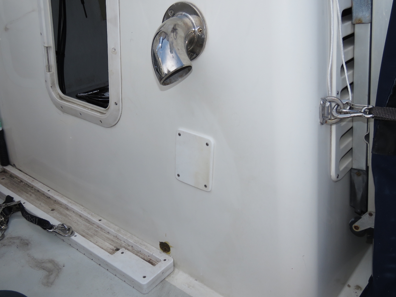
A couple of days after we arrived into Newport, we found the breaker for the pilothouse 120V outlets had tripped. We investigated all the electronics plugged into the PH outlets but the breaker would still trip. We eventually unplugged everything and it still tripped so it had to be a bad breaker or a circuit problem. We got out the boat wiring diagram to investigate more deeply and noticed there were two more outlets on the circuit up on the boat deck. Stepping outside, the source of our issue was pretty obvious: a socket mounted on the side of the stack was showing some blackening.
Over the next few days, we sourced parts, replaced the socket box and also resealed the engine exhaust cooling vent directly above it. Details of the job from April 1st through April 5th, 2017 follow.
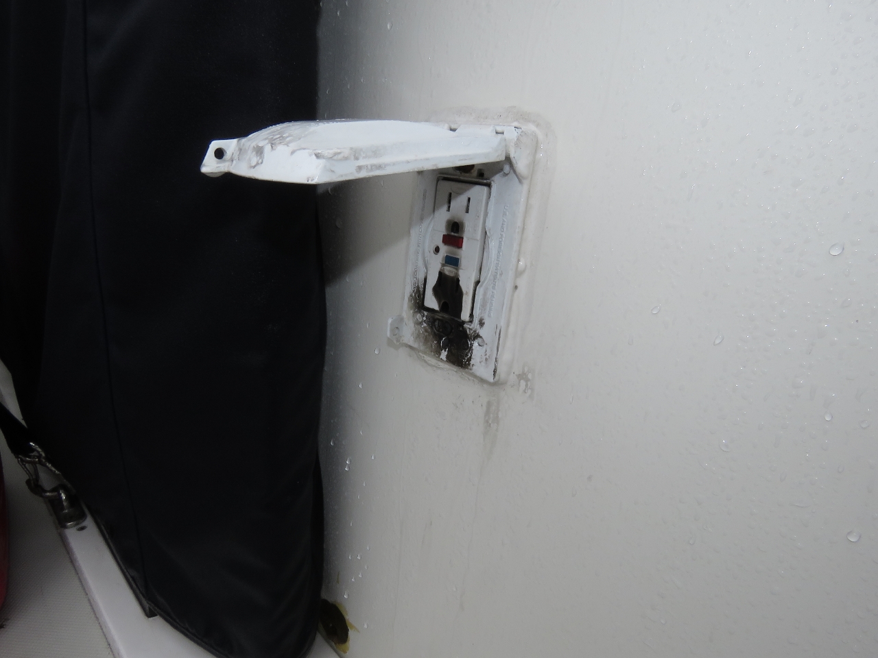 |
Socket
Position: -71 19.05, 41 29.10
The damaged socket is the same we’d founds a loose wire at when investigating a water leak in the stack while in Plymouth, NH. Two problems is too many, so we will replace the socket entirely with a water proof variant and replace the wiring that runs to the socket to ensure that all is new and dry. The parts are ordered from Amazon Prime and, for now, we have an extension cord bringing power up to the PH.
|
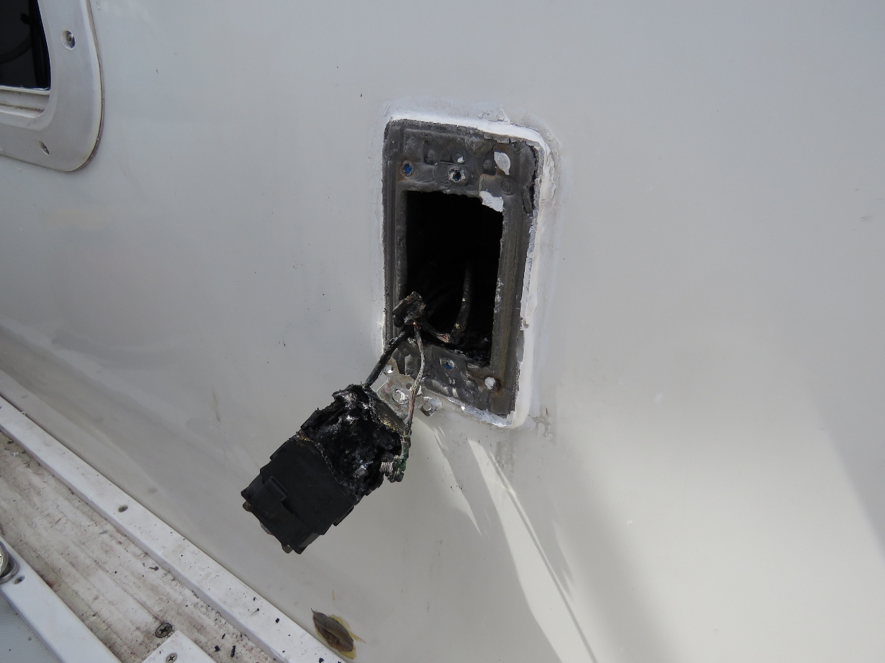 |
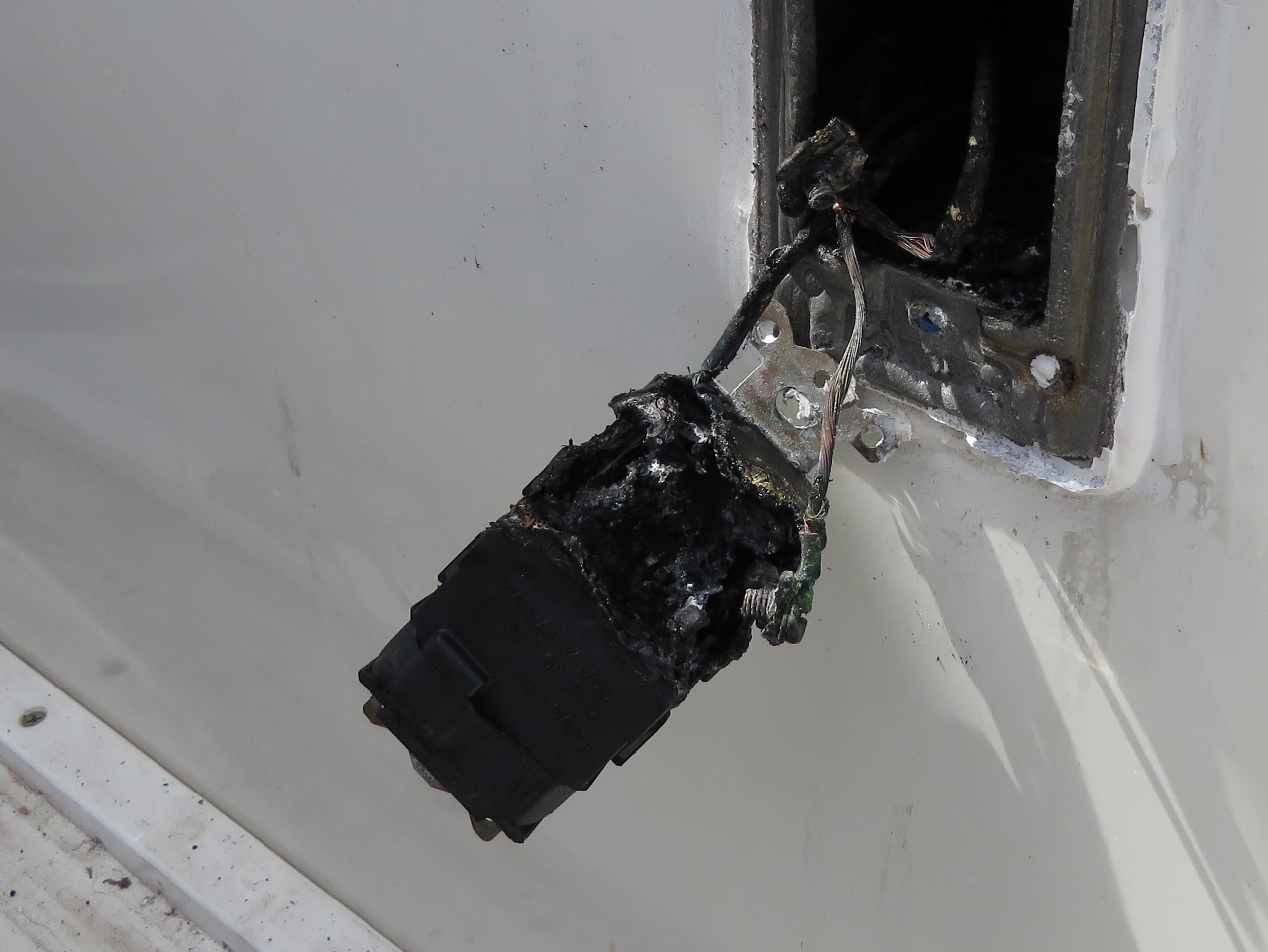
Burned Socket
Position: -71 19.05, 41 29.10
Our Amazon Prime order with replacement parts for the burned socket arrived this morning, so we started in on the repair. The damage was more extensive than we’d realized. It looks like the worst possible failure mode where some current still flowed between poles in the socket but not enough to trip the 15A breaker in the pilot house. 15A is a lot of power and can produce dangerous heating. It appears that it was leaking power between the poles for quite some time prior to the breaker eventually opening. The lower quarter of the GFCI burned away and two inches of the feed wires were burned.
We don’t know if the GFCI failed to open, but the socket still leaked current between the poles perhaps due to water intrusion. It’s a good thing that the breaker protected the circuit correctly. If that breaker had failed to open, then there is a 30A breaker “north” of the 15A but that would require twice the fault current to release. |
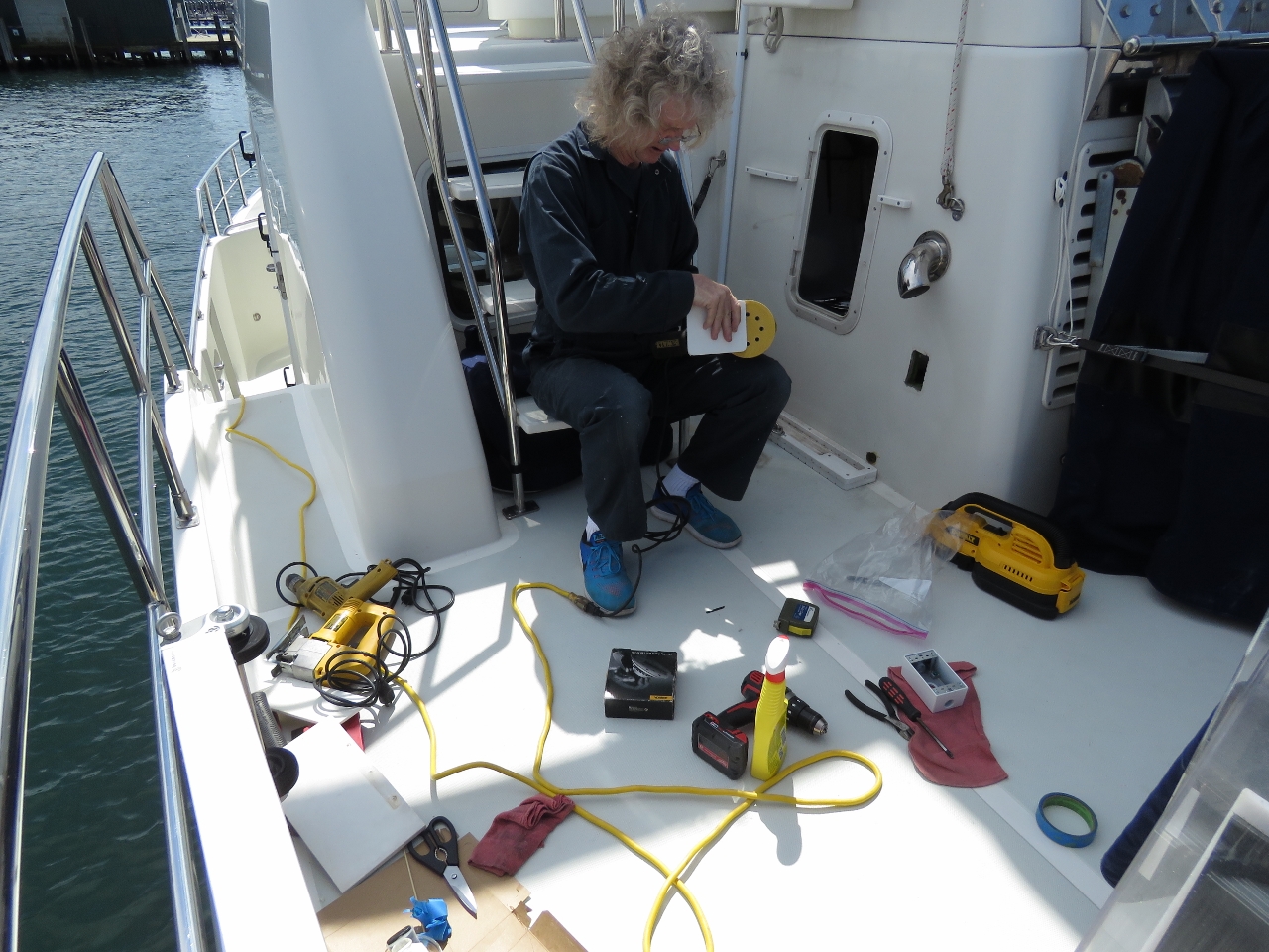 |
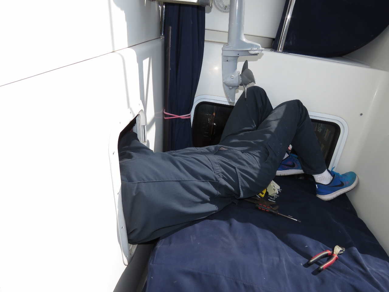
Work in Progress
Position: -71 19.05, 41 29.10
We removed the old burned-up unit, cleaned up the 5200 that sealed the square stack opening and any loose core material, and sealed up the stack core with epoxy. Here James is smoothing down a marine-board plate that we’ll use to cover the hole and mount the new box.
|
 |
Plate
Position: -71 19.05, 41 29.10
The plate in place, covering the hole where the old socket mounted into the stack.
|
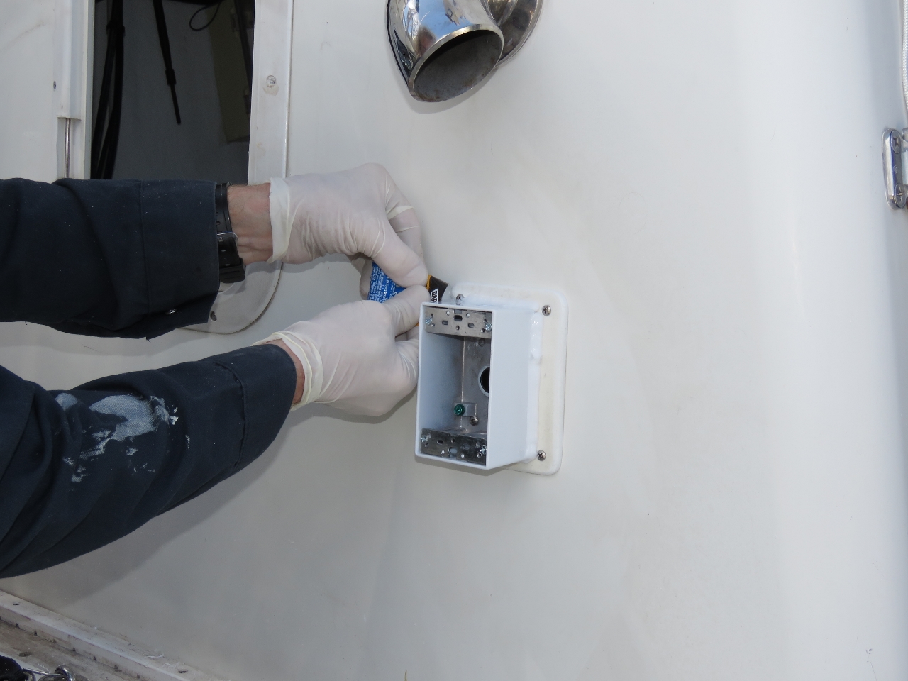 |
New Box
Position: -71 19.05, 41 29.10
Sealing the new outdoor-safe power box to the plate with silicone. It’s a 100% sealed-up aluminum box with only two openings. The one in front will be sealed by an outdoor-certified socket cover and one in the back will be sealed by an outdoor-safe power wire gland.
|
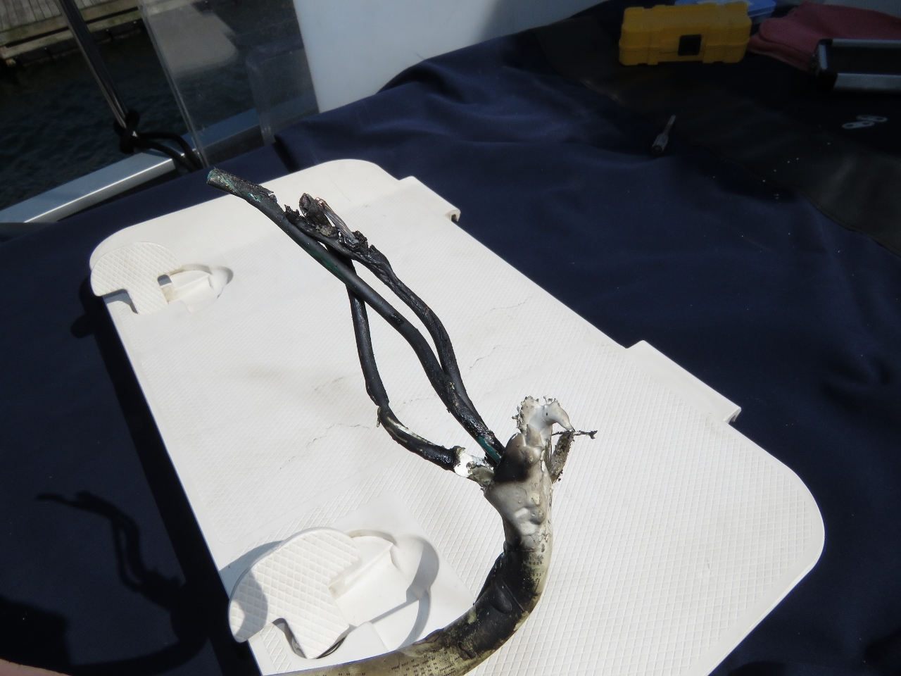 |
Burned Wire
Position: -71 19.05, 41 29.10
This is the original feed wire that connected to the back of the socket. Two inches were burned.
|
 |
Wiring Socket
Position: -71 19.05, 41 29.10
James pulling a new feed wire to replace the damaged one.
|
 |
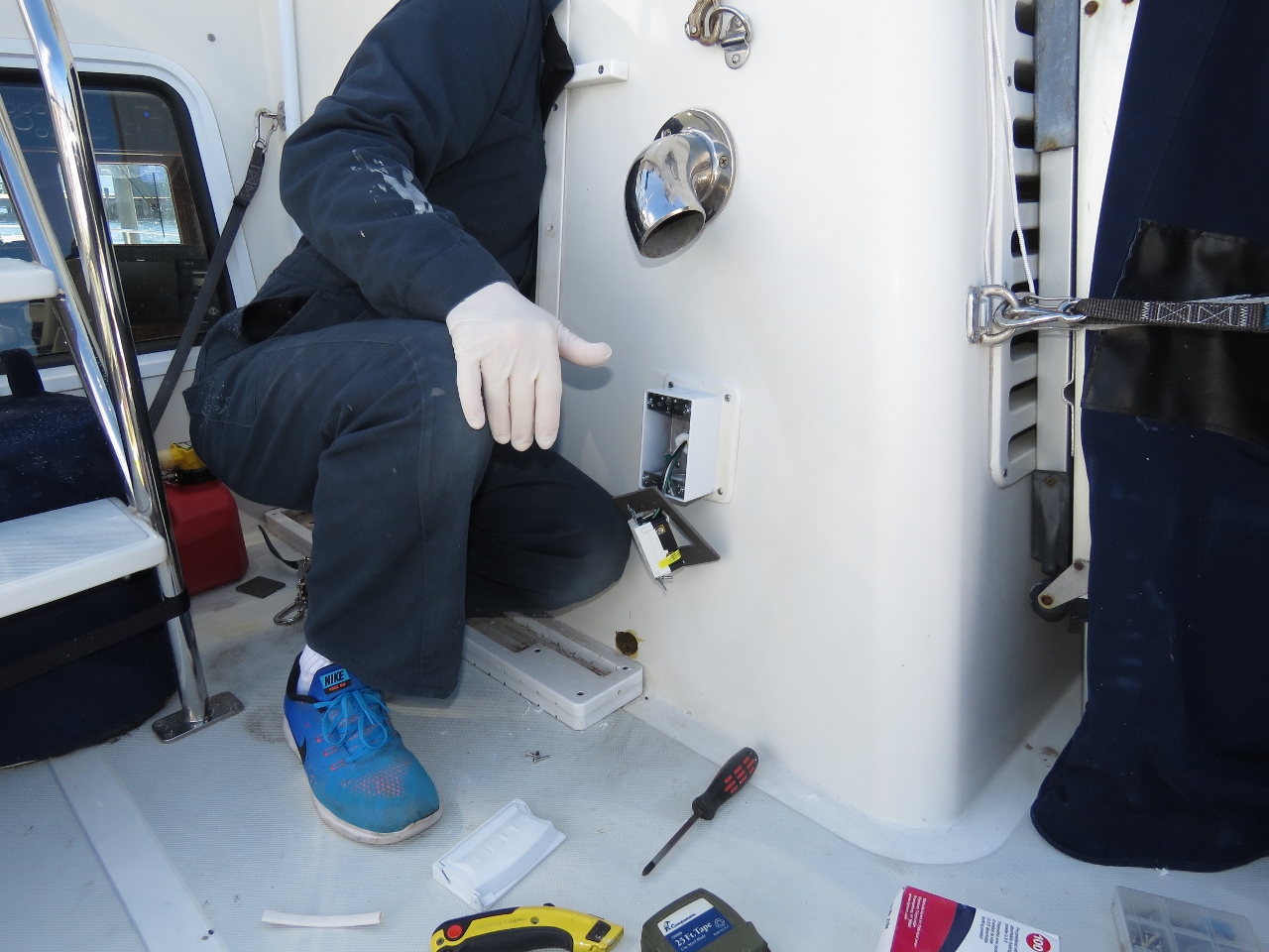
Connecting Power
Position: -71 19.05, 41 29.10
Connecting the other end of the feed wire to the junction box. There are no easy-to-get-at places in the stack, but this one was particularly difficult.
|
 |
Completed Job
Position: -71 19.05, 41 29.10
This finished job looks pretty good and definitely is weather-safe.
|
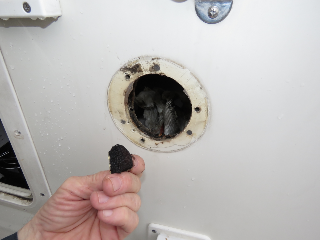 |
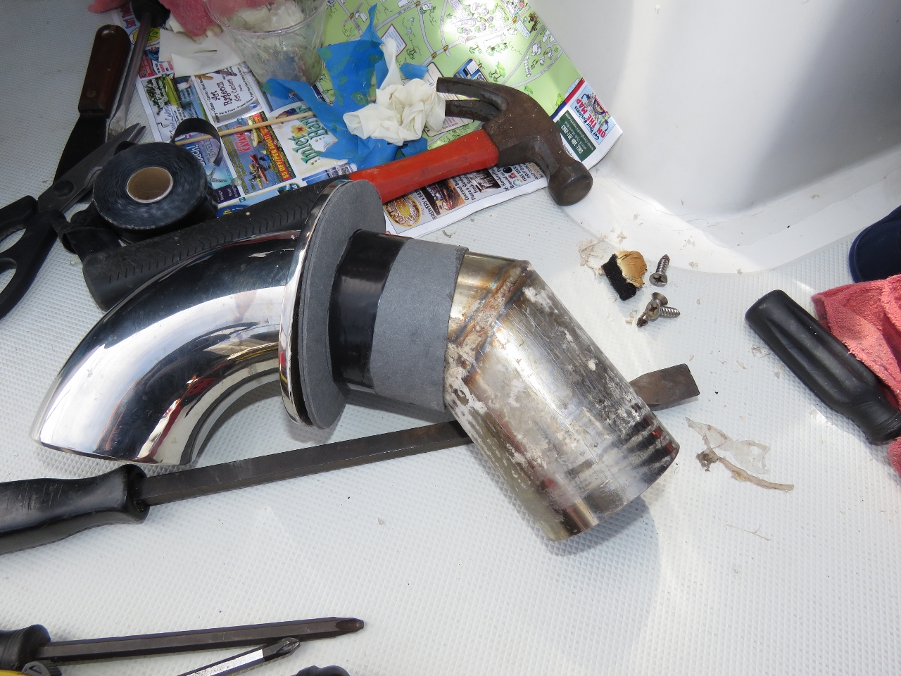
Vent
Position: -71 19.05, 41 29.10
The burned socket was well-sealed against the elements both inside and outside the stack, so it wasn’t clear what caused the water-induced current leakage. Closer inspection of the engine exhaust cooling vent directly above the socket revealed that the vent is sealed on the outside but there is exposed foam core on the inside. The water is flowing down the inside of the stack when it’s really wet, entering the foam core of the stack at the exhaust cooling vent, and flowing down to the socket. Since the socket was well sealed against water entering (or exiting), it just filled up with water.
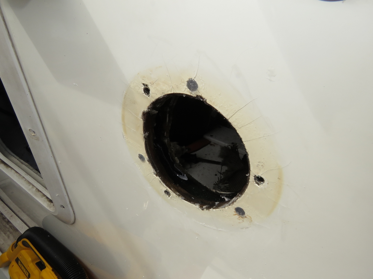
It’s bad news to have water entering foam cores, we had another job ahead of us to remove the exhaust vent, cut back the foam, and epoxy fill the void to seal off the core and then replace the fitting. We started that job this morning and on removing the vent we saw that the foam core temperature had been high enough over the years to darken it. This vent is the exit for the exhaust stack cooling system. Air leaves this vent surprisingly hot—we’ve seen temperatures as high as 250°F. There’s an air gap between the pipe and the surrounding fiberglass, and the only point of contact is the flange. We chose to mitigate the temperature issue in three parts: 1) cut back the foam core a half-inch beyond the edge of the fiberglass and seal it with epoxy, leaving an even large air gap to the foam, 2) put two layers of fibrous high-temperature exhaust gasket between the flange and the fiberglass, and 3) put an insulating layer of the same material around the pipe where it exits through the side of the stack, while still leaving an air gap. |
 |
Epoxy
Position: -71 19.05, 41 29.10
We cleaned up the core and sealed it with five-minute epoxy.
|
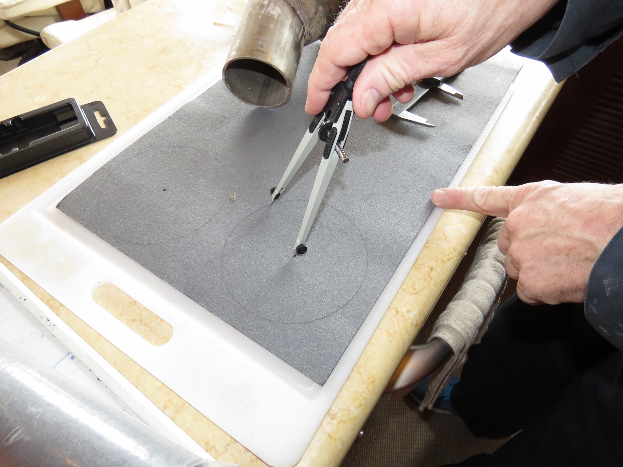 |
Gasket
Position: -71 19.05, 41 29.10
Preparing to cut the insulating fibrous high-temperature exhaust gasket.
|
 |
Collars
Position: -71 19.05, 41 29.10
Two gasket collars installed on the exhaust vent.
|
 |
Ready to Re-install
Position: -71 19.05, 41 29.10
The now-insulated stack vent ready to re-install. The fibrous insulation material is exhaust gasket, rated well beyond 1,000°F. The strip of tape used to hold the insulation at the hole through the stack is rated at 450°F, so has lots of engineering headroom for this cooling air application. The tape is only needed to hold the insulation in place around the pipe during installation.
An additional potential gain from this work is we used to have a small water leak, just a small drip, into the engine room during very heavy rains. It appears that water may have been coming in through the foam core at the exhaust cooling vent. We’ve had one very large rain since then with no evidence of leakage. |
With today’s commercial HVAC equipment, the ECM’s tend to do everything they can to save the equipment.
I know we’ve been able to pin down what normally would seem at first glance to be a nuisance trip to failing disconnects and breakers using a infra red camera.
I don’t know if that would be something you’d find a use for on Dirona especially one like I carry however, if you get one run off a Android or I Phone they tend to be fairly cheap.
That’s good advice. I’ve seen thermal imaging used to find faulty server power supplies in data centers. I’ve also seen them used to chase down improperly torqued power distribution connections. Thermal imaging seemed pretty effective for both applications but when I’ve looked in the past, they were pretty expensive for personal use. I do have a IR heat gun and once used it to detect a poor 24V connection that was running hot.
I do periodically scan my power distribution bus and the back of the breaker panel with the IR gun but a thermal imager would be more effective. I see that Flir now has a unit (Flir C2) down below $500: https://www.amazon.com/FLIR-C2-Compact-Thermal-Imaging/dp/B00T9RANUC/ref=sr_1_3?ie=UTF8&qid=1493896602&sr=8-3&keywords=thermal+imaging.
Prices are coming down and having one might make more sense. There is a chance we’ll be underway Monday morning so I can’t order one today but, if we do get delayed further by weather, I might order one of these. Thanks for the suggestion Steve.
That looks like a good unit but if you are interested in something lower in price here are a couple of links to consider.
Android
http://www.thermalcameraexperts.com/Seek-Thermal/CompactXR-Android/Industrial-Thermal-Cameras/?Source=googleshopping&gclid=CLOam8ub19MCFY66wAodx3ACFQ
IPhone
https://www.amazon.com/Seek-Thermal-XR-Imager-iOS-Apple/dp/B00SSZ5KPY/ref=sr_1_1?ie=UTF8&qid=1493934589&sr=8-1&keywords=thermal+imaging+for+iphone
Thanks for the pointer Steve. That looks like a good way to reduce the cost by around 1/2. My Android phone USB type-c connectors don’t appear to be supported yet by Seek but presumably they will have support coming.
After years of waiting to buy a thermal camera, I finally purchased a Seek Reveal Pro. This unit has a much higher resolution (320x 240) than the inexpensive FLIR units, and at $700 was just inside my target budget. The UI is a little wonky but the sensor works very well. I’ve used it for everything from finding insulation issues in the RV to location doggy accidents on the carpet.
One issue is that at the moment the Reveal Pro still cannot generate radiometric images, but I was promised by Seek that this feature is coming in a firmware update.
Good catch Adam. I thought the Flir C2 was 640×320 but, in fact, what Flir is doing is overlaying a 640×320 visible light camera over a very low resolution thermal sensor. The actual thermal sensor in the Flir C2 is only 80×60. The approach of blending a visible and thermal camera is a nice one but I’ll want a far higher thermal sensor resolution. Thanks for pointing that out.
Seems like a bit of a design flaw not to have the outside outlets on a separate (lower-rated) breaker? Or a separate switch in the pilothouse, for that matter.
Jamie, I had this socket added while the boat was commissioned — it’s not part of the standard Nordhavn install. Generally for outside sockets or inside, they typically are on 15A circuits in North America so nothing unusual there.
The new junction box is a much better design unlikely to let water in. As an extra level of protection we have put arc fault and ground fault circuit interrupters on all circuits on Dirona whether they are inside or outside. All circuits are not protected. So, looking at this socket, we have it sealed, it is a AFCI/GFCI socket, then we have a 15A breaker and then “above” that we have a 33A breaker. Overall I like the new design.