As we completed our previous attempt at changing the engine mounts, we still had two major issues. The first was the front mount material seemed thicker than what originally was on the boat, and the second issue was we couldn’t jack the engine up far enough to remove the old rear mounts. We spoke with the general manager of Poly Flex, the engine mount manufacturer, and he immediately proposed good solutions to both.
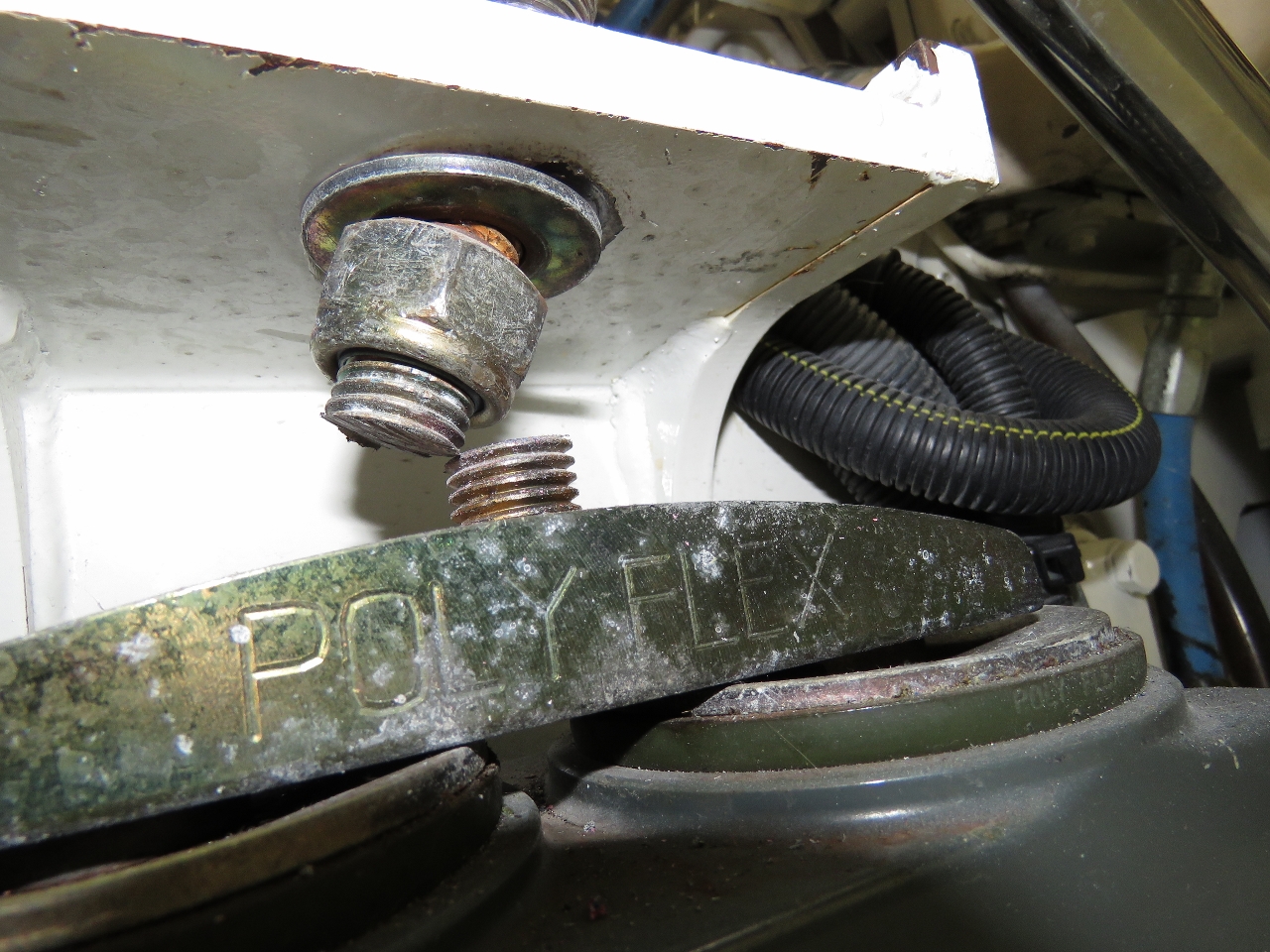
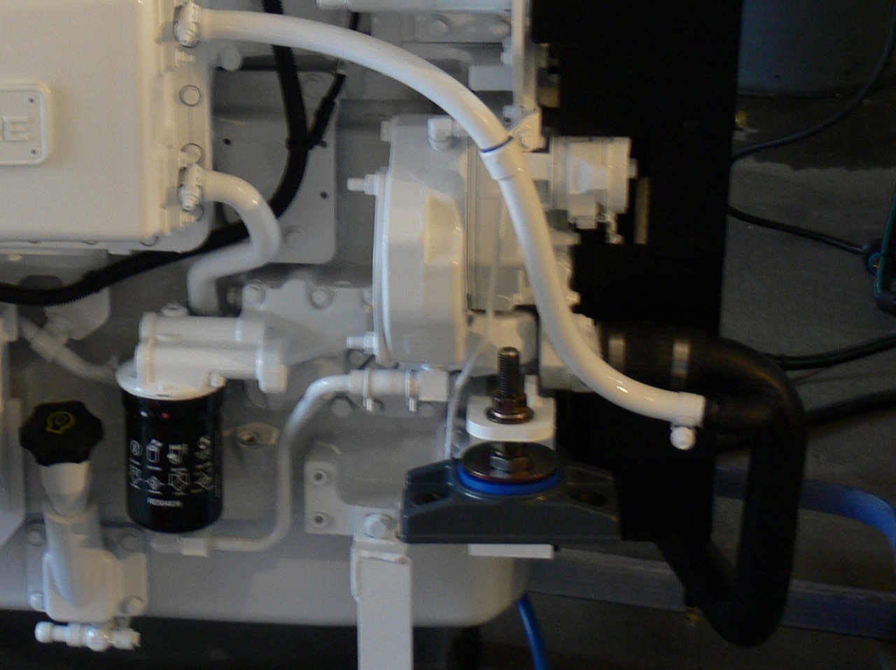
When our engine left the engine distributor in Seattle, it had the standard Poly Flex mounts as shown in the first picture below. But when the boat was delivered, the mounts were far lower profile, as shown in the second picture below. What must have happened was the boat yard had trouble getting the engine low enough, and replaced the normal Poly Flex mounts with the low-profile variant. Poly Flex said “no problem” and air-freighted the correct low-profile mount inserts to us.
|
|
We also described the problem of not being able to easily lift the engine high enough to get the old rear mounts out and the new ones in. The challenge is that the engine won’t lift high enough at the rear, without disconnecting the prop shaft and possibly the exhaust, to remove the old mounts. Again, we got the same “no problem” from the Poly Flex general manager. He said we could just cut the old studs off and he’d send us a mount package with a removable central stud, and those parts went out in the same shipment. That’s impressive service.
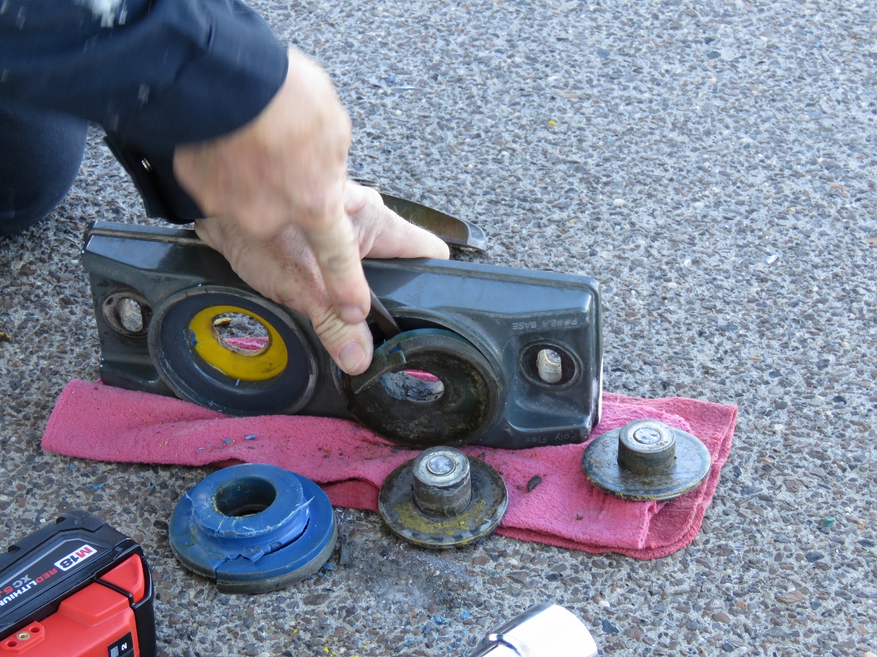
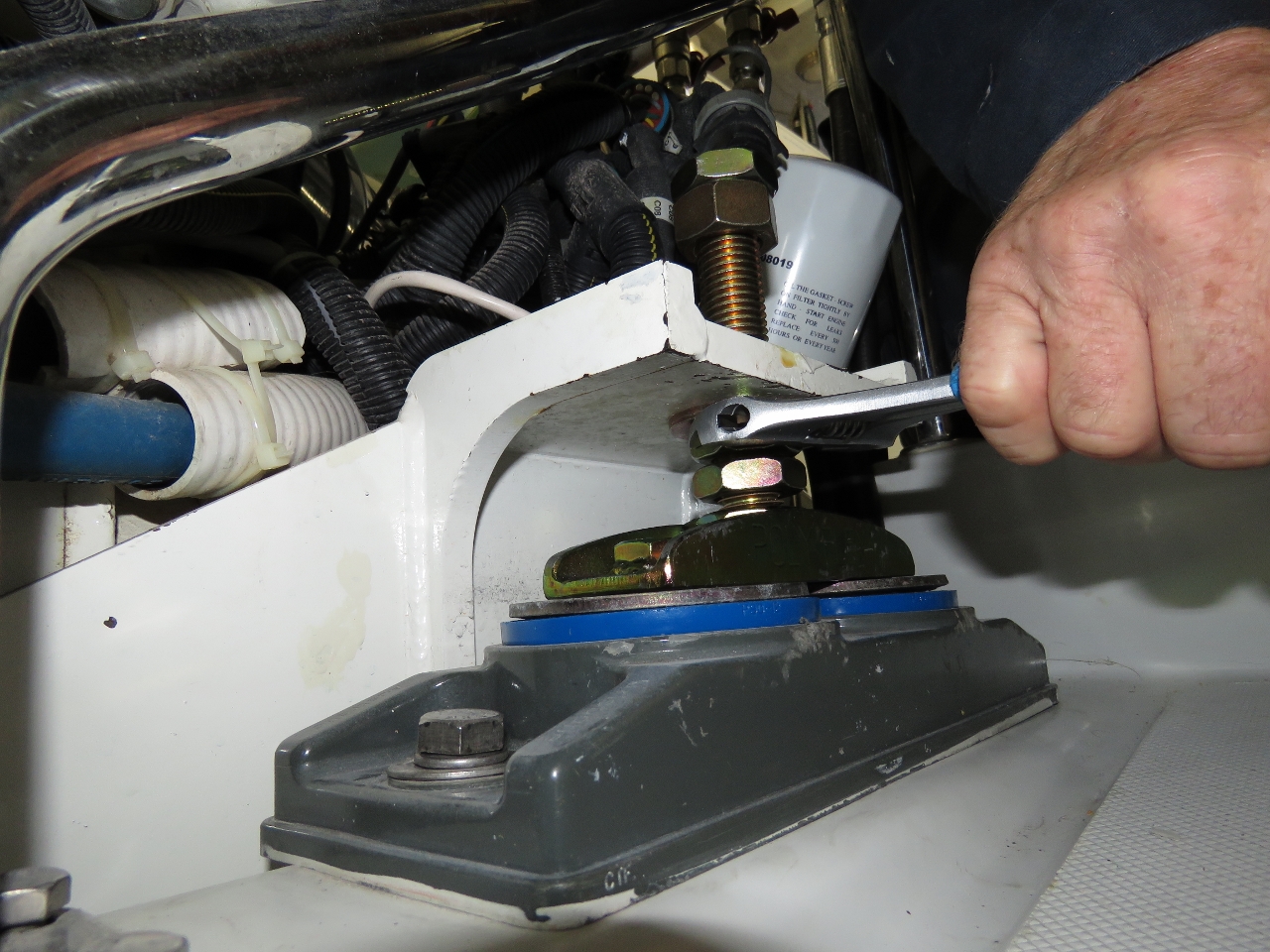
The parts arrived quickly and, since we were planning to be in Southwest Harbor, Maine for a few days, we got going on “take two” of changing the engine mounts. The front ones came off quickly using the same approach as before with the hydraulic jack. We lifted each front corner of the engine, removed the old mounts, disassembled them, swapped out the mount insert, and then reinstalled the mount in under thirty minutes total for both mounts.
|

|
On the rear mounts, the first challenge we ran into was the under-engine clearance is so tight that we couldn’t get the hydraulic bottle jack under the rear. We contemplated lifting the engine using an engine hoist attached the the deck above, but this looked challenging.
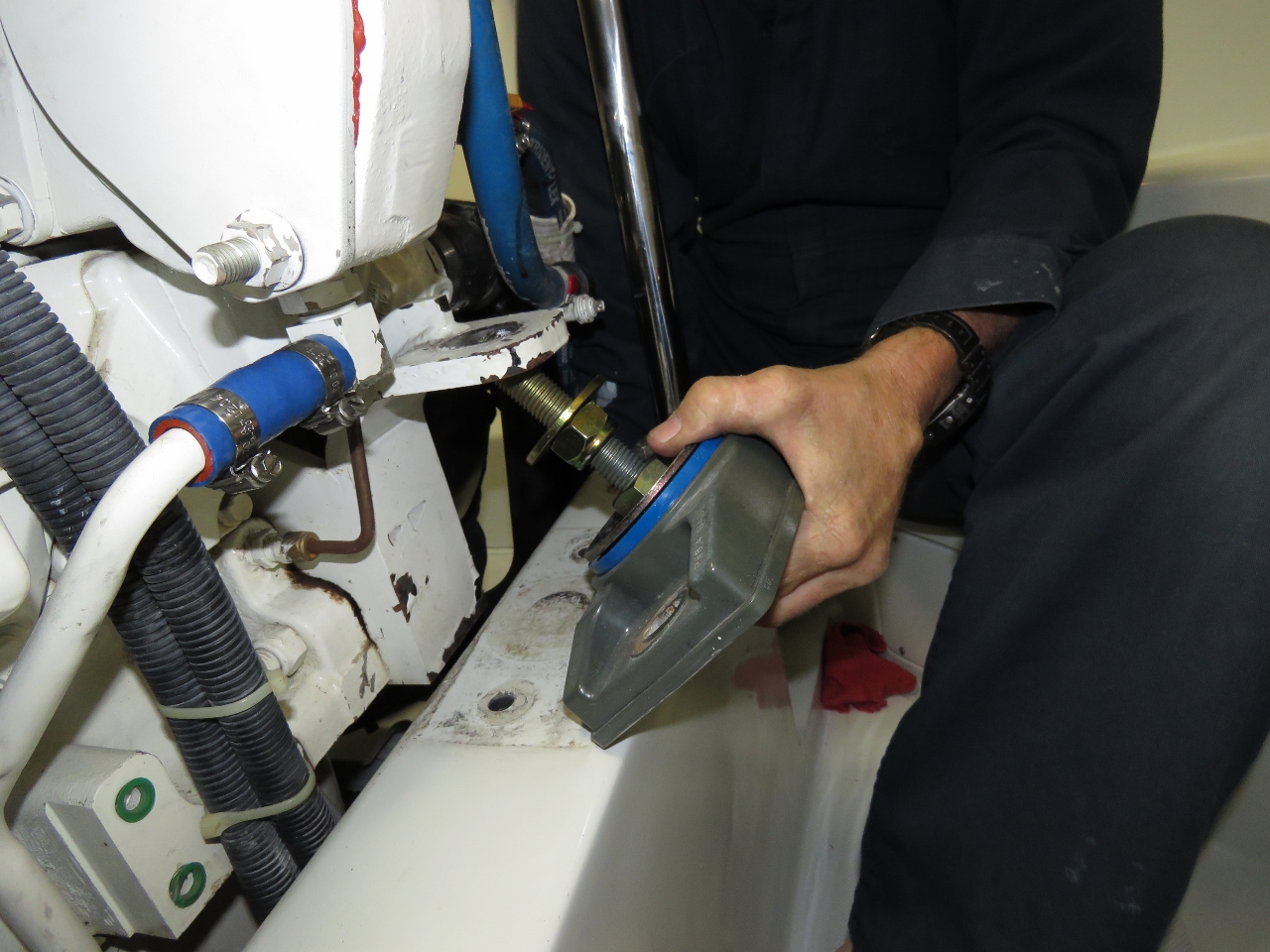
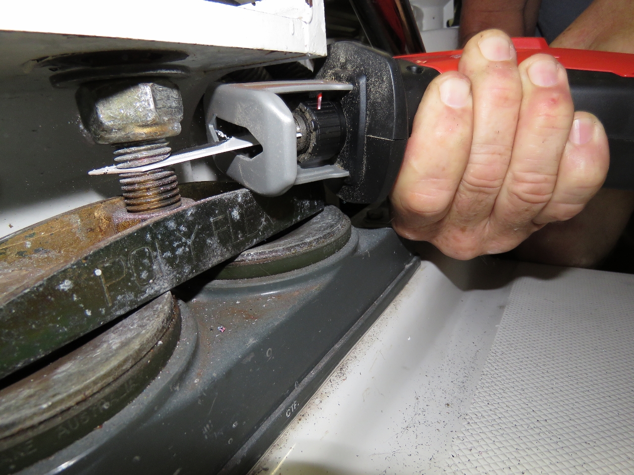
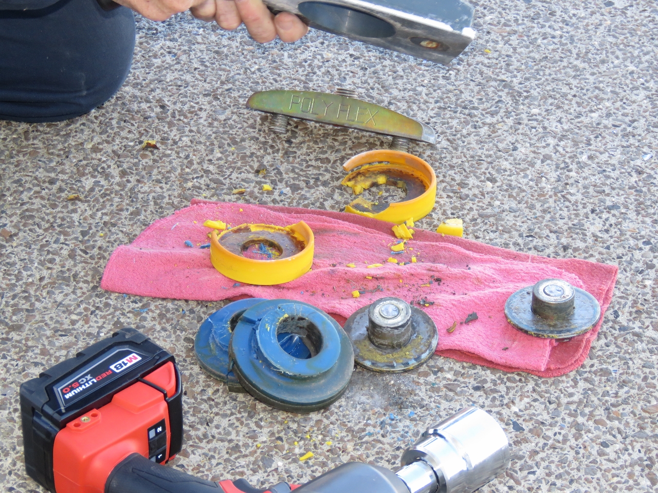
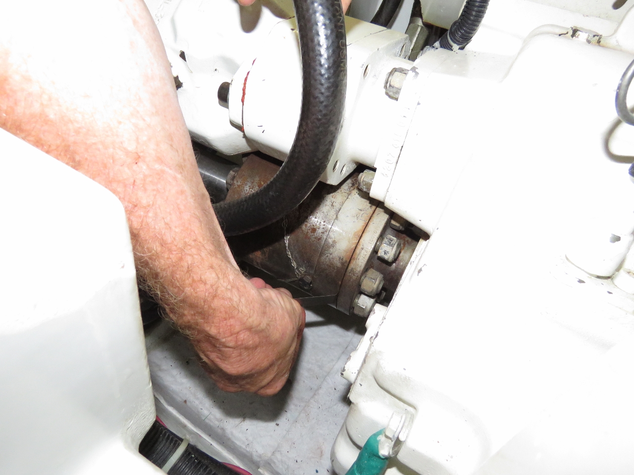
The solution was surprisingly simple. Rather than lift the engine, we left the engine in place and lowered the rear mount to be changed such that it was no longer bearing any weight. All the engine weight was supported by the other three mounts. This worked super well and unloaded the mount to be changed in seconds. Then we cut off the stud using a large Milwaukee cut-off saw and slid out the old mounts. It felt crazy to be cutting off the engine mount, but it made for an easier change. And with the new removable-stud mount hardware, the mount inserts can now be changed in minutes rather than hours.
|
|
|

|
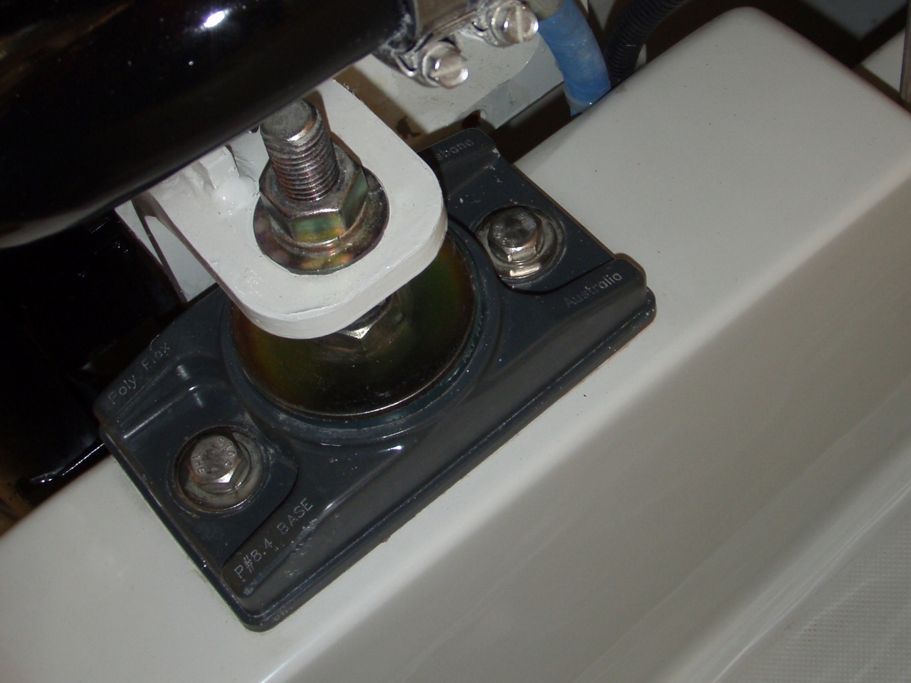
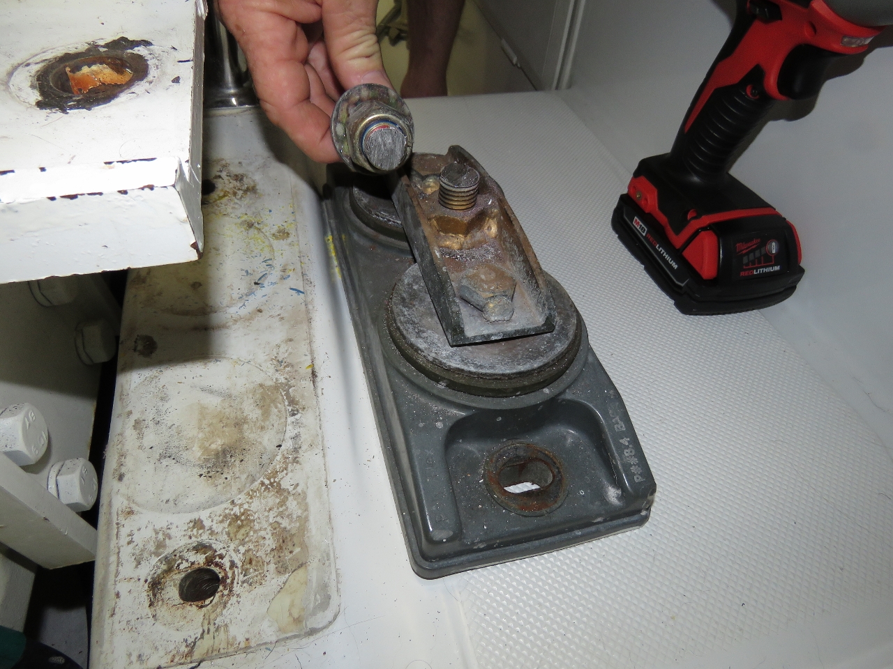
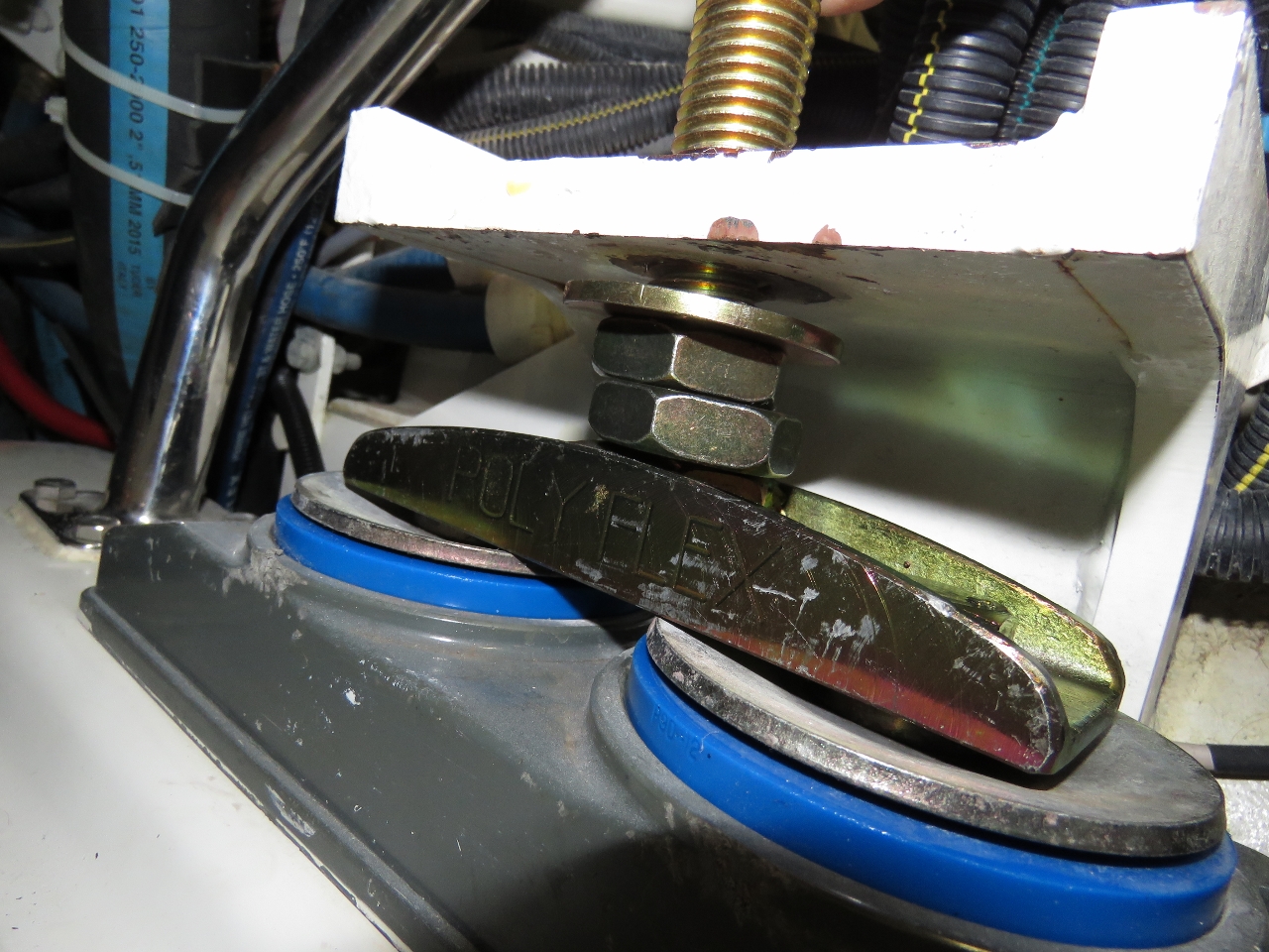
This job took less then five minutes. But, we ran into another problem. In the picture immediately above, looking at the bottom of the engine mount you can see two large nut and spacers that need to come off to replace the mount insert. They appear to have been welded in place, excessive Loctite had been applied, or potentially they had rusted in place, although there’s no evidence of water or rust. It’s hard to know the exact problem, but we applied hundreds of foot-pounds of torque and they simply were not coming off.
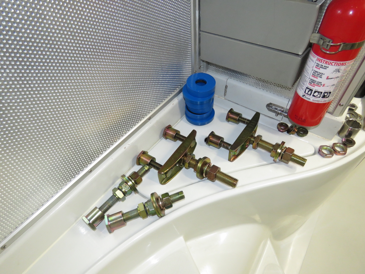
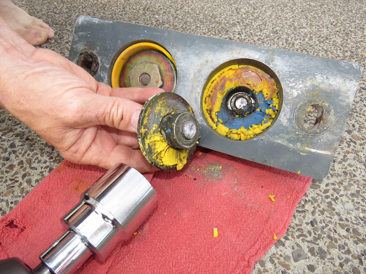
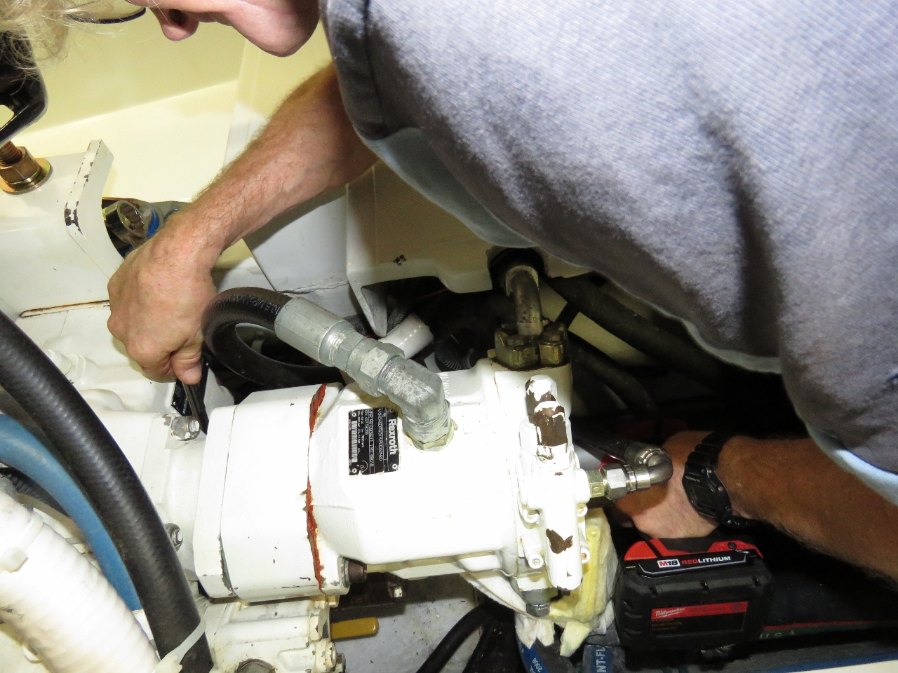
The solution to this one was surprisingly simple as well: use an impact wrench with one of our new jumbo sockets to undo them, knowing they will eventually either unscrew or the stud will shear off. If they unscrew, great. If not, it doesn’t really matter since we’re replacing the mount bridge which includes these studs. All four broke rather than unscrewing, so we were right that they were not coming off. But the good news is that it didn’t take long. The impact wrench delivers progressively more force trying to unscrew the bolt until each eventually sheared.
|

|
The rear mounts weren’t in quite as bad shape as the front mounts, but definitely in need of replacement. They had already started to disintegrate and drop chunks.
|
|
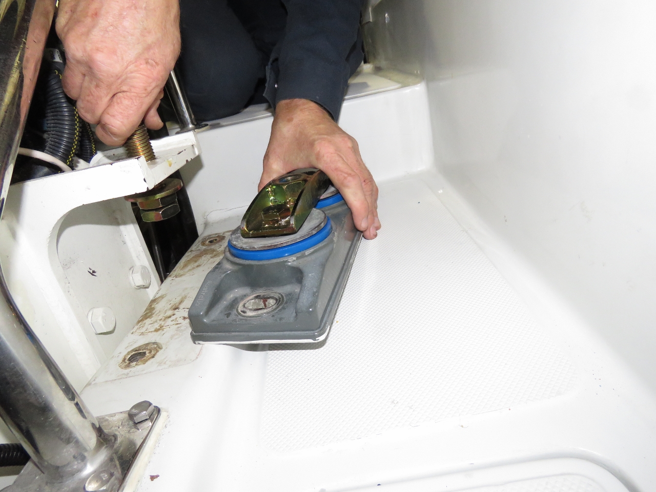
The easy part was taking the mount bases and the new parts and reassembling the mount package and reinstalling it. With the new configuration we could change the mounts in under an hour and then only have to align the engines. Future jobs will be easy. But, we don’t expect to have to replace these mounts for another 8,000 hours. And since Poly Flex has made some materials improvements over the last seven years, it won’t surprise us a bit if these new mounts last even longer.
|
|
|
|
Once the mounts were replaced, it was time to align the engine and transmission assembly. This is considered by many to be a difficult job but it’s really not that hard. It does require accurate measurement and patience, but it’s not difficult.
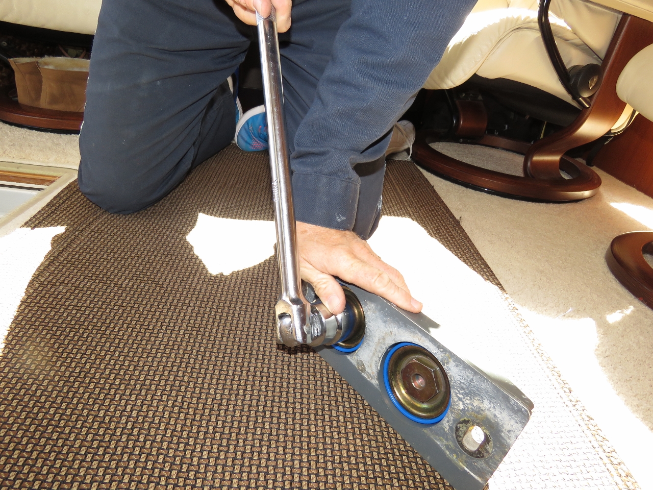
The first step of engine alignment is to loosen off the large 24mm wrench sized bolts that attach the flange on the end of the prop shaft to the flange on the transmission output shaft. Once this has been loosened up, we did the alignment in two phases. Phase one is to adjust the aft end of the engine such that the prop shaft is central in the prop shaft opening. For this phase, we just returned the engine to exactly where it was when the boat was delivered from the yard measured using calipers. The rear mount adjustment procedure is similar to the front mount adjustment procedure described below.
At this point, phase one is complete. The prop shaft is central in the shaft tunnel when mated up to the transmission flange, but the engine and transmission assembly is not in line with the prop shaft. Phase two is getting the engine and transmission assembly exactly inline with the prop shaft. And, when we say exactly, it needs to be within 0.001″ per inch of shaft diameter. That’s within 0.00225″ for our 2 1/4-inch prop shaft. We prefer to be somewhat more precise so aimed to get as close as we possibly could to 0.001″ of run out.
The actual alignment measurement is made using feeler gauges between the transmission output shaft flange and the prop shaft flange. We measured at each of four quadrants ninety degrees apart. The quadrant with the most space is the direction the engine needs to move. If the bottom quadrant is largest, then the front of the engine needs to go down or the rear of the engine up. These fine adjustments we did only by moving the front mounts up and down and for these we’re only turning the mount stud nuts by a fraction of a turn. Initially we were turning 1/4 turn but, as it got close to correct, we were adjusting by as little as a 1/2 a nut flat which is only 1/12 of a turn.
In the example above, when the bottom quadrant has the most clearance, we need to move the front of the engine down. If the top had the most clearance, we would do the opposite. Up and down is fairly easy. But, if the left or right quadrant had the most clearance, the engine would need to be slide slightly sideways which is a lot less precise that adjusting screws on a mount stud. We loosened the bolts holding the engine mounts to the bulkhead and and used a pry bar to move the engine in the direction we wanted to rotate it.

|
|
If the left quadrant facing the transmission showed the largest gap, then the engine and transmission needs to rotate very slightly with the front moving left and the rear of the engine moving right. It turns out it’s actually fairly easy to move the 2,000 lb engine/transmission assembly using a pry bar once the mounts are all loose. What’s hard is keeping the motion small enough. Even tiny shifts have a huge impact on shaft alignment. Small amounts of force do nothing and then just a bit more force moves the assembly too much. The trick is to listen carefully and apply the smallest amount necessary such that you can hear slight clunk as the assembly just slightly shifts.
Once it shifted in the desired direction, we bolted everything back down, turned the shaft a couple of times by hand and remeasured the gap at the four quadrants. Again, we found the largest and repeated the process. Eventually, the process converged.
We chose to keep adjusting until the gaps only differed by one thousandth of an inch (0.001″). That’s a bit more precise than absolutely required and, if the prop shaft is not absolutely straight, it won’t even be possible. Once the four clearances measured sufficiently close to each other, we re-torqued the bolts holding the transmission flange to the prop shaft flange and the job was done.
We’re slow at this process and it’ll take us around three hours but it’s not a complex nor difficult process. Having changed parts to allow the engine mounts to be serviced more easily, we could now change all four mounts and align the engine in under four hours.

Dirona now is running as smoothly as we can ever remember, possibly better than since new.
James,
How come Dirona’s now running at least as smoothly as when new? Was the at-delivered prop misalignment that much greater than the results of your efforts?
Or is this the racing-car mechanic talking again?
Alex asked “How come Dirona’s now running at least as smoothly as when new?” What I mean is the prop shaft appears to be as well aligned as when the boat was first delivered and perhaps better.
I’m sure the boat was expertly aligned when it left the boat yard and we certainly had no concerns with prop alignment when we got the boat. New boats are lifted in and out of the water, spend time in a cradle on a frieghter and then are relaunched back into the water. It wouldn’t be entirely surprising that a new boat would need to be re-aligned after it has resettled after delivery but, as I said, Dirona seemed great when delivered and we had no noticable issues.
Hi James- We are all learning allot from you. I think you may be the ultimate technican/engineer when it comes to the systems repair/modifications on Dirona. I am constantly amazed at your tenacity, approach and mad skills. Nordhavn should be paying attention to your upgrades/repairs/maintenance to improve their machinery and electronics on their boats. Congrats on another great posting.
Thanks for the kind words Gary. Like the math proofs the professor writes up on the board at the front of a first year math class, they look pretty easy as he writes them up but, what you don’t see is the hours spent trying to come up with the final proof. So too with repair work. Some jobs are straight forward and “just work” but most bring challenges of some sort. If you don’t have the right tools, you need to put it back together and wait for a chance to get the right tools and try again or improvise with less than adaquate tools. Don’t have the right parts? Again, either improvise and find a way to make the old component work again or put it back together and wait for an opportunity to get the right parts. Because we value our time, we try hard to anticipate faults and to always have the right pats aboard. We sit a bit lower in the water than most 52s :-).
I thank Nordhanvn nearly every day since, unlike most builders, they actually produce designs that, with rare exceptions, actually can be serviced. It’s amazing how many boat builders build boats “around” components such that even the most skilled technician can’t do a thing without tearing up the entire boat. I also thank Nordhanvn for using components that are good fits for the application and don’t require constant replacement. Our rule on our previous boat is to think through each component replacment and, if the failed part isn’t strong enough, to find a way to use a better component rather than just replace the part that died. On Dirona, we find most components are well selected and we just need to change them rather than upgrade and or redesign. Much easier, much less work, and much less frequently in need of service.
Because we use our boat a lot and we document all the service that gets done, most weeks there is something being done. But, having owned another boat and put 4,100 hours on it, I can’t tell you how happy we are to have an easier to service boat with stronger components requiring less service.
Amazing amount of work to do crouched and on your knees. Bottle jack on the stringers? I would not have thought to cut the old bolt. It may be a time saver for the future as I have to change mine soon too. The Velvet gap is .003 in. at 90° intervals. I cannot imagine being as precise as Dirona especially in the tight space. Very impressive. How are the wing mounts holding up? Same material?
I bet the documenting took longer than the actual motor mount change! The engine coercing however…
Timomthy said “I bet the documenting took longer than the actual motor mount change!” — the next one for certain will go that quickly. But this one sure didn’t. The biggest challenge when doing a job for the first time is the risk of not having the right tools and having to improvise, not having the right parts and having to improvise or take on the job again once the parts are available, and lack of experience. I generally find I’m about 4x faster the second time but the challenge is, when servicing a single boat, the most likely outcome is you will do most jobs once but very few of them more than once.
The wing engine mounts are of the more conventional design where a metal stud is held by a rubber insulating material that is cast into a metal external housing that gets bolted to the stringer. The wing mounts have only 750 hours and allmost all of those hours were drivig hydrauics rather than propulsion. That’s fairly low hours and “pushing” a boat ahead in a propolsion application is harder on the mounts than generator and hydraulic applications that just hold the engine but don’t have to tranfer propulsion loads. The wing mounts will probably last another 6 to 8 years before failing on time rather than use.
The Poly Flex engine mount design is an unusual one in that it uses advanced polymer isolators with composit bases. Most are rubber between a metal base and supporting stud. The Poly Flex design is super configurable where you can set them up for a wide variety of different load and space considerations. That of course is both a strenght and a weakness in that it took some research to find the right parts for our boat. However, they appear to be a very well made mount and, if I’m right that the next set goes for 10 years or more, I’ll be pretty impressed with the longevity as well. I’m generally pretty impressed with the Poly Flex design with my only critisism is, when they start to break down, they go fairly quickly. As we are currently set up, they are easy to change and this set went 8,000 hours which isn’t bad at all. In the 7 years since ours were originally installed, Poly Flex has made design changes both in the thrust washer design and in the characteristics of the thermoplastic used so there is a good chance the next set will go considerably longer than the just under 7 years and 8,300 hours these went.